29
8. Load Connection Example
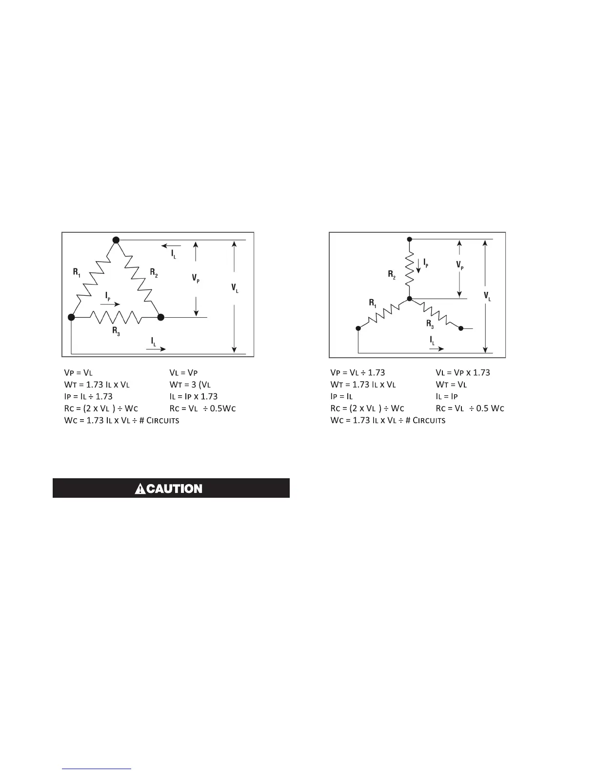
The following wiring diagrams and electrical equations are provided as a reference for this manual. The three phase
equations shown can be applied to any balanced Delta or Wye (star) circuit. The terms used in the equations are
identified below:
Vl = Line Voltage Wt = Total Watts
Vp = Phase Voltage R1 = R2 = R3 = Element Resistance
Il = Line Current (Amps) Wc = Wattage per Circuit (Equal Circuits)
Ip = Phase Current (Amps) Rc = Circuit Resistance in Ohms Measured Phase to Phase
2
÷ R
1
)
2
2
2
÷ R
1
2
2
The model C4 has specific dipswitch settings
for the various load configurations. Incorrect-
ly setting with a mismatch load configuration
could result in unpredicted results. Please re-
fer to section 7.7 or the Load Connection ex-
amples for these proper dipswitch settings.