C
ONNECTOR
-_
~./C
WA
T
ER
THRO
W
ER
SHAFT
AND
BEARI
NG \
~~'
~
'?
'\--
--
FAN PUllEY HU8
T""'
R
ATU'IE
GAUGE S
EN
DI
NG
U
NIT
LOC
K RI
NG
PLUG
IMP
ELL
ER
SE
AL
ASS
EM
8l Y
5.5,,
16A
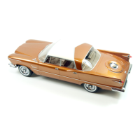
Fig. 1 -
Woter
Pump (Exploded View)
COOLING
SYSTEM
The cooling system
for
the
1956 Models is fun-
damentally
the
same
as
the
1955 :Models.
Service
procedures outlined in
the
1955 Serv-
ice Manual
D-1543.1
will apply to the 1956
Models with the exception of removing and in-
sta
lling the new plastic impeller,
The
water
pump
shaft
bearing
lock
spring
has
been elimi-
nate
d
(Fig,
1),
The new
shaft
and
bearing
as-
sembly
will
be
a press fit in
the
water
pump
housing,
N
OTE:
So
m.
e
01
the
1955
water pumps
may
be
used
in
the eal'l y
1956
cal'
S, The
1955
water
pum.
p
ha
s a slot in the neck
of
the water pu
mp
body for the bearin g ?'etainer, The press fit type
pump w
ill
have this slot eli1ninated,
WATER PUMP IMPELLER
Removal
S
upport
pump housing
by
clamping
fan
pulley
hub in
vi
se and remove the cover plate and
gas
ket.
20
NOTE:
It
is not necessar1j
to
?,emove
shaft
and
bearing
Msembly from pump housing
to
remove
impelle1',
Use a suitable chisel to
break
the plastic por-
tion of impeller away from metal insert,
(Start
ncar
metal
insert,)
Remove
parts
of
seal assembly by sliding
them
over
shaft
and
attach
puller, Tool C-3476.
to remove metal insert.
Installation
Install new seal assembly into impeller and se-
cure
with lock ring,
With
support
pump
housing suppo
rted
on
shaft,
press impeller on
shaft
with
suitable
sleeve which will
direct
pressure
on metal in-
sert
only.
CAUTION: When pre8sing
on
impellel', support
the pump housing in such a
~vay
that pressure is
being applied
to
the
shaft
and
not
the housing,
If
preSSU1'e
is
applied
to
housing damage
to
the
shaft
and bearing assembly 1uill1'esult,
_
...
--
I
I
 Loading...