95
Example:
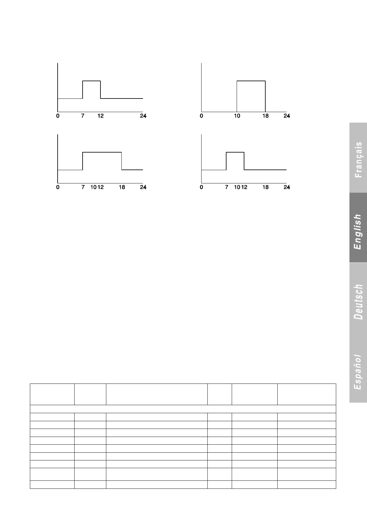
Prog 1: 7-12h CSG1-CSG2 MTW TF
Prog 2: 10-18h CSG1-stop MT TF
Holiday zone: 10-08 / 30-08 : stop
Prog 1: MTWTF Prog 2: MTWTF
Setting 1 Setting 1
Setting 2 Setting 2
Result:
Status: MTWTF Status: MTWTF
Setting 1 Setting 1
Setting 2 Setting 2
Saturday and Sunday not being selected in the hourly programming, the unit is therefore stopped.
The unit is stopped between 10th August and 30th August, this period being selected as holiday zone.
27 COMMUNICATION PROTOCOL
A) Communication medium
- RS485
3-pin connector on terminal 1 of terminal block J11: A or +
Terminal 2: B or –
Terminal 3: connected to earth
for shielding if desired
Two lights provide information on the status of the transmission
(see Section 3.1, control board)
- D50 → Receive LED. Usually off; flashes when a message is
received by the board.
If this light remains on, the bus is reversed. Swap terminals 1 and
2 on J11.
- D52 → Send LED. Usually off; lights up when the CPU sends a
message over the bus.
B) Transmission mode
Serial, asynchronous, half duplex, RTU mode.
- 1 start bit,
- 8 data bits,
- The parity is set via parameter P702,
The number of stop bits is set via parameter P703,
- The transmission speed is set via parameter P701,
- The unit number on the bus is set via parameter P705.
Coding of analogue values
Standard 32-bit IEEE format (2 registers).
Order of values:
- If P704 = No → low order, high order.
- Si P704 = Yes → high order, low order.
Function codes used.
1 or 2: read n bits
3 or 4: read multiple registers (16 bits)
5: write one bit …………..
6: write register function………
8: read diagnostics counters
11: read event counter
15: write n bits
16: write multiple registers (16 bits)
Note: the write functions are enabled if parameter P103 is set to
"Remote, BMS…"
Error codes:
1: function code unknown
2: address incorrect
3: data error
27.1 Registers accessible by customer
Registers accessible in read-only mode (Functions 3 or 4)
Evaporator inlet temperature
Evaporator outlet temperature
Available with versions
09.00 and higher
P285 Heating mode runtime (in hours)