76
- The two fans 1 on circuit 1 will be controlled by stage 1 on circuit 1, motherboard terminal block J3 (terminal 5)
- Fan 2 on circuit 1 will be
controlled by stage 2 on circuit 1,
motherboard terminal block J3
(terminal 6)
- Fan 3 on circuit 1 will be
controlled by stage 3 on circuit 1,
ADD 2 board terminal block J3
(terminal 7)
- The two fans 1 on circuit 2 will be
controlled by stage 1 on circuit 2,
ADD 2 board terminal block J3
(terminal 5)
Fan 2 on circuit 2 will be
controlled by stage 2 on circuit 2,
ADD 2 board terminal block J3
(terminal 6)
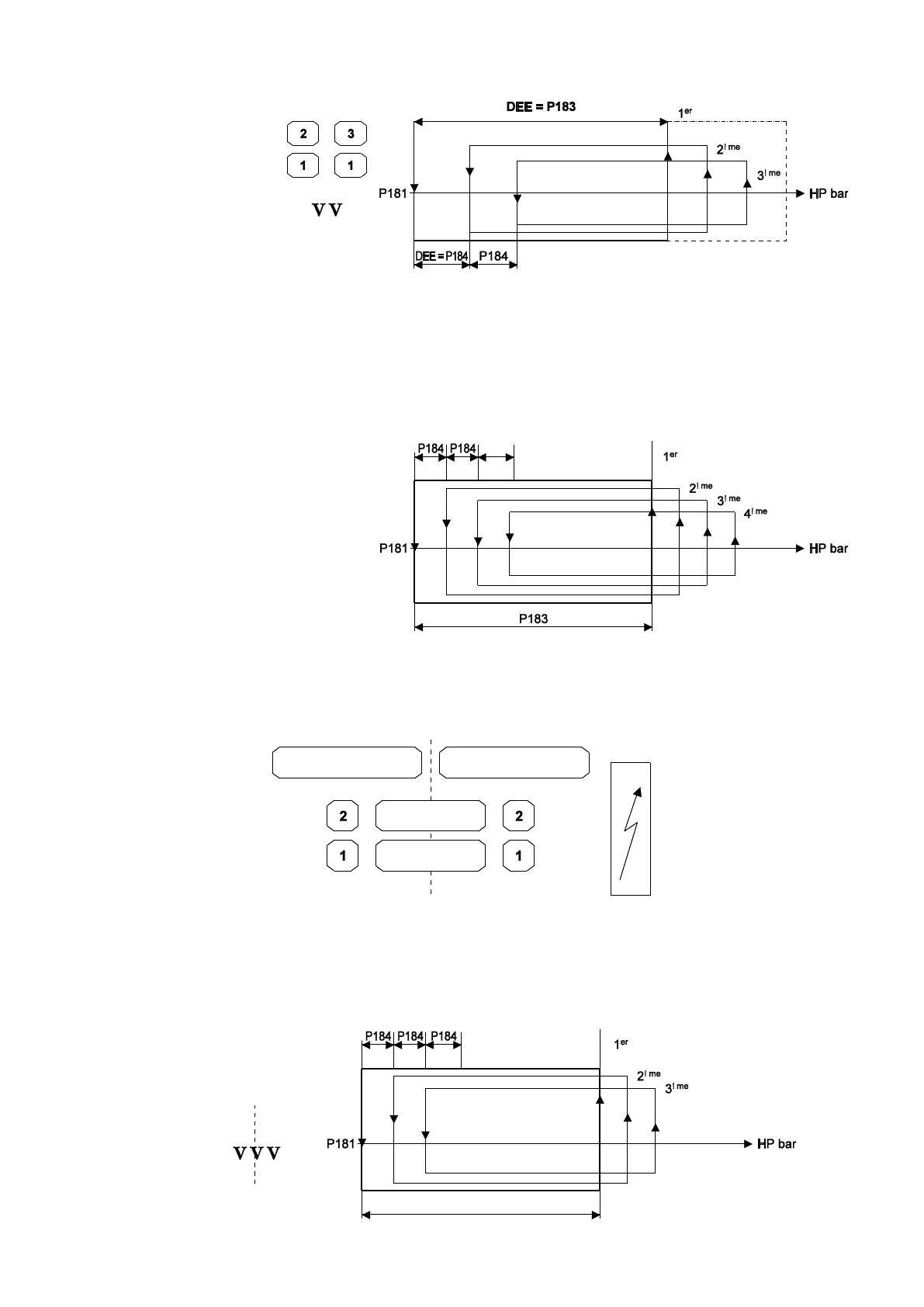
- Fan 3 on circuit 2 will be controlled by stage 3 on circuit 2, 1er =: stage 1, 2ème = stage 2, 3ème = stage 3,
ADD 2 board terminal block J3 (terminal 8) DEE = Interstage differential
B) On/Off, where (P21 = No), P10 = propeller and P11 = intertwined
- Control mode is turned on as soon as a compressor stage is running on the unit.
- If one of the two circuits is shut off (by a temporary or permanent fault, or control fault or other fault), the fan continues to operate using the
pressure from the circuit this is still on.
When both refrigerating circuits are on, the fans are turned on and off by the circuit with the highest pressure.
Fan 1 will be controlled by stage 1, motherboard
terminal block J3 (terminal 5)
Fan 2 will be controlled by stage 2, motherboard
terminal block J3 (terminal 6)
1er = stage 1,
2ème = stage 2,
3ème = stage 3,
4ème = stage 4
C) On/Off, where (P21 = No), P10 = propeller and P11 = intertwined
- Control mode is turned on as soon as a compressor stage is running on the unit.
- Stages 1 and 2 are controlled by each circuit.
- Common stage 1 is turned on as soon as the first control stage for circuits 1 and 2 is turned on.
- Common stage 3 is turned on as soon as the third control stage for circuits 1 and 2 is turned on.
Fan 1 on circuit 1 will be controlled by stage 1, motherboard
terminal block J3 (terminal 5)
Fan 2 on circuit 1 will be controlled by stage 2, motherboard
terminal block J3 (terminal 6)
Fan 1 on circuit 2 will be controlled by stage 1 on circuit 2, ADD
2 board terminal block J3 (terminal 5)
Fan 2 on circuit 2 will be controlled by stage 2 on circuit 2, ADD
2 board terminal block J3 (terminal 6)
"Common" fan 1 will be controlled by common stage 1, ADD
2 board terminal block J3 (terminal 7)
"Common" fan 3 will be controlled by common stage 3, ADD
2 board terminal block J3 (terminal 8)
1er: stage 1
2ème: stage 2
3ème: stage 3
2 condenser fan modules per circuit = 3 single phase stages