EasyManuals Logo

CIAT Connect 2 User Manual

CIAT Connect 2
101 pages
To Next Page IconTo Next Page
To Previous Page IconTo Previous Page
Page #10 background imageLoading...
Page #10 background image
8
3.5 Connection via RS485 serial port for BMS or control console and Multiconnect with 500 kW module
For connection to a CMS, refer to document 3991049.
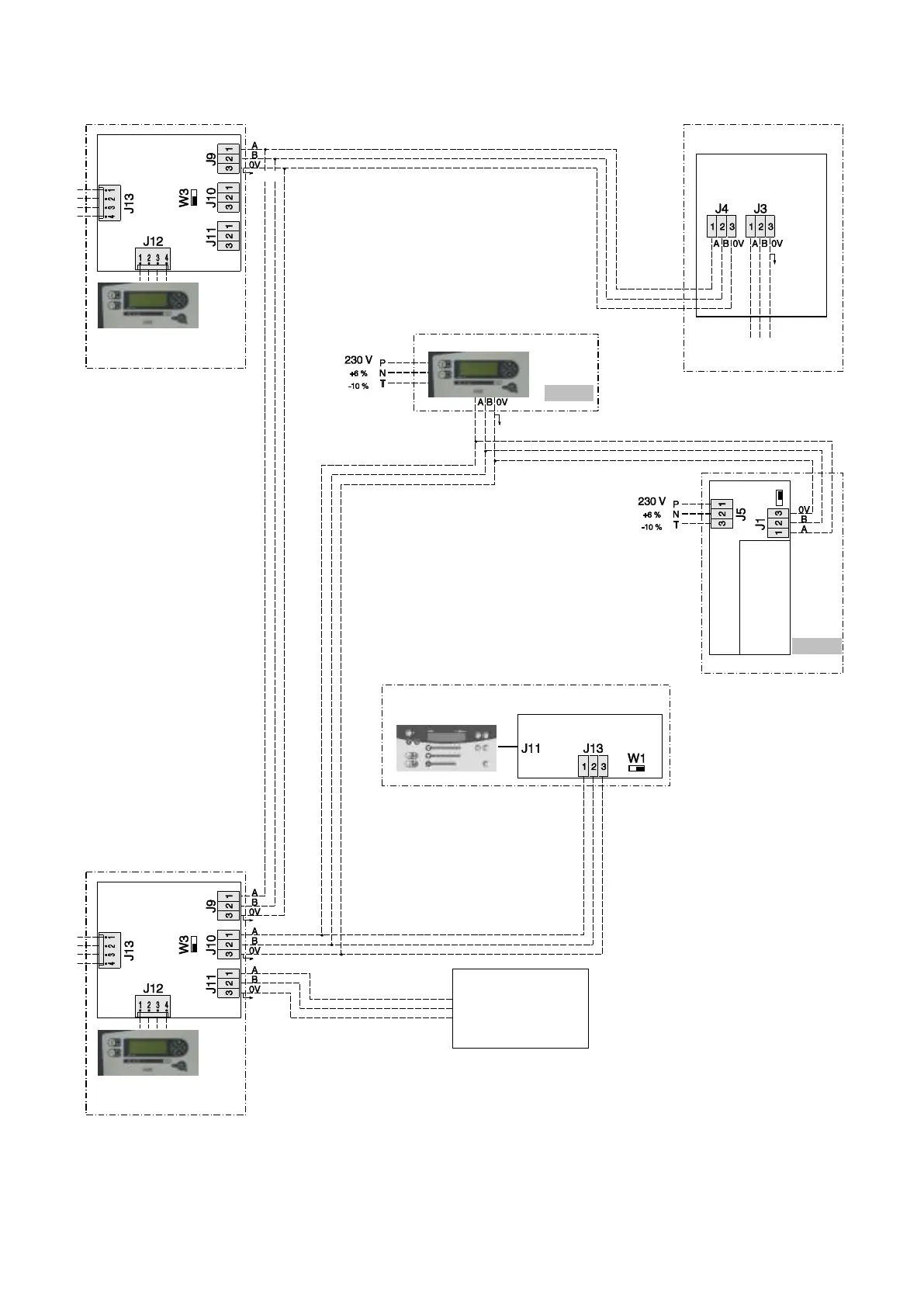
Identification of Modbus connection terminals
1 A or +
2 B or
3 Earth (shield)
Detail B
End of line
resistance switch
The switch is set to the right by default.
On the last machine in the loop, it must
be set to the left.
Detail A
End of line
resistance switch
Position of switch when only one
option is connected to the RS-485
output on the main board
Position of switch when several options
are connected to the RS-485 output on
the main board
RS-485 PLC
BMS
2-wire RS-485
Max. length:
1000 m
Main relay
board
Additional
relay board 1
See detail A
Optional
Installed on unit
Shield
To
additional
board
CONNECT 2 main board
Unit 2
Local console
See detail B
Shield
Shield
Installed on unit
Shield
To
additional
board
CONNECT 2 main board
Unit 1
Local console
See detail B
Remote control console
Shield
Optional
MULTICONNECT
main board
Shield
RS-485 link to BMS
(Modbus protocol)
AEROCONNECT board
UNIT
Local console

Table of Contents

Questions and Answers:

Question and Answer IconNeed help?

Do you have a question about the CIAT Connect 2 and is the answer not in the manual?

CIAT Connect 2 Specifications

General IconGeneral
BrandCIAT
ModelConnect 2
CategoryControl Unit
LanguageEnglish

Related product manuals