5
TERMINAL BLOCK J8 (analogue inputs)
1-2 Refrigerant temperature sensor, circuit 1
2-3 10 K suction temperature sensor, circuit 1
4-5 10 K liquid temperature sensor, circuit 1
6-7 50 K discharge temperature sensor, stage 1, circuit 1
7-8 50 K discharge temperature sensor, stage 2, circuit 1
9 +5 V power supply for pressure sensor
10 0-5 V input - HP sensor
11 0-5 V input - LP sensor
12 Common for pressure sensors
TERMINAL BLOCK J9
Link for chiller or MULTICONNECT
TERMINAL BLOCK J10
Remote control console, relay board link - AEROCONNECT
TERMINAL BLOCK J11
BMS link
TERMINAL BLOCK J12
Local console link
TERMINAL BLOCK J13
Link for additional boards
TERMINAL BLOCK J14
Ethernet link for PC
On/off input specifications: 24 V - 15 mA
On/off output specifications: 250 V - 2 mA
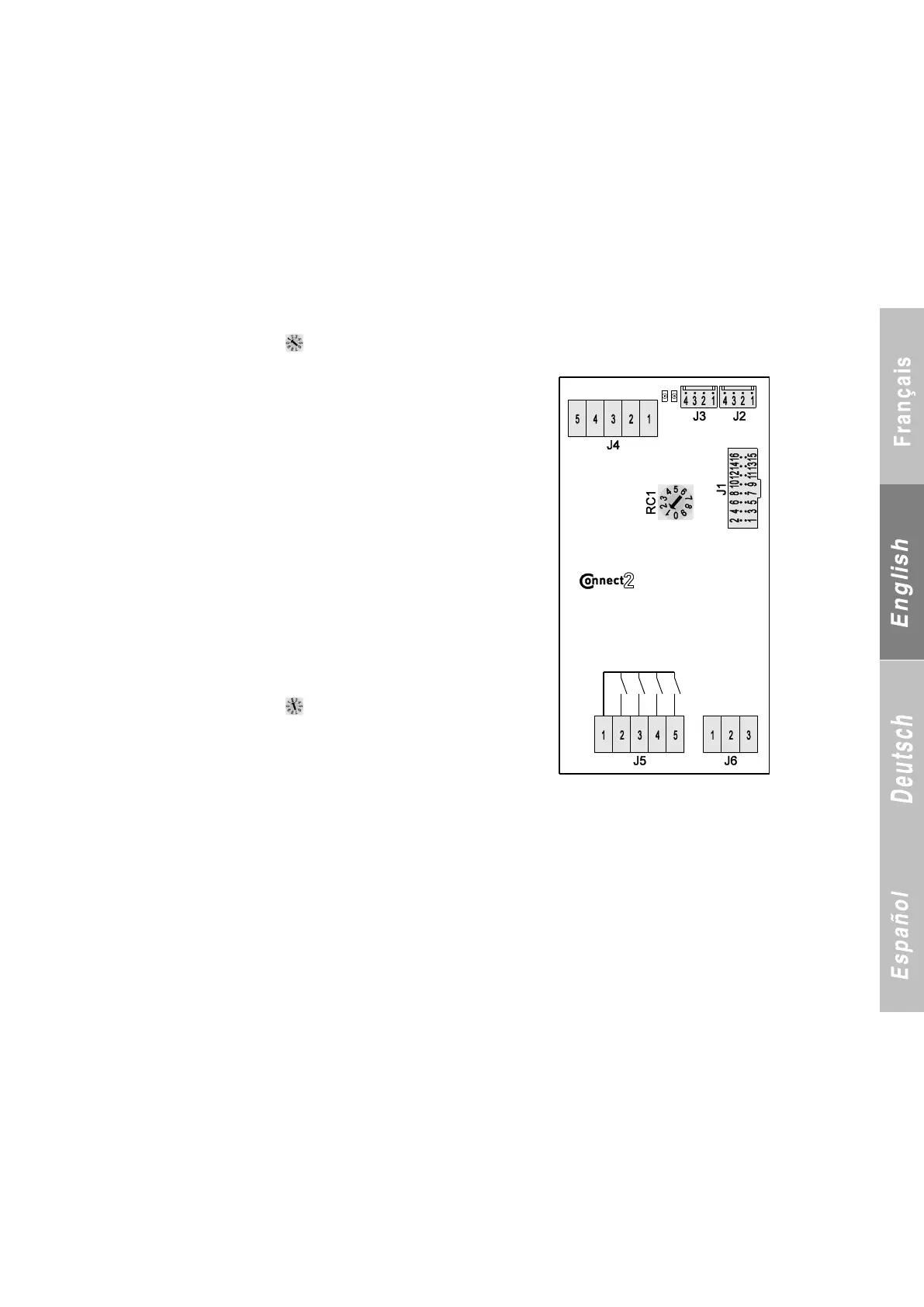
3.2 Additional board 1
3.2.1 Rotary switch set to position 1 - One circuit reversal use or recovery frost protection
TERMINAL BLOCK J1
Flash Memory connector
TERMINAL BLOCK J2
Link with motherboard or another additional board
TERMINAL BLOCK J3
Link with another additional board
TERMINAL BLOCK J4 (on/off inputs)
1-2 Heating/cooling selection input if unit type (P2) = reversible air-to-water
and number of circuits (P3) = 1
2-3 Available
4-5 Available
TERMINAL BLOCK J5 (on/off inputs)
1 Common to all outputs
2 Circuit 1 reversing valve control
3 Circuit 1 pressure balance valve control
4 Recovery frost protection heat trace cable
5 Reverse rotation control for fans
TERMINAL BLOCK J6 (analogue inputs)
1-2 Temperature sensor, coil A, circuit 1
2-3 Temperature sensor, coil B, circuit 1
3.2.2 Rotary switch set to position 2 - Use of electric auxiliary heaters
TERMINAL BLOCK J1
Flash Memory connector
TERMINAL BLOCK J2
Link with motherboard or another additional board
TERMINAL BLOCK J3
Link with another additional board
TERMINAL BLOCK J4 (on/off inputs)
1-2 Programmable input (P113)
2-3 Fault 1, electric stages
4-5 Fault 2, electric stages
TERMINAL BLOCK J5 (on/off inputs)
1 Common to all outputs
2 Electric stage 1 output
3 Electric stage 2 output
4 Electric stage 3 output
5 Electric stage 4 output
TERMINAL BLOCK J6 (analogue inputs)
1-2 Available
2-3 Available