13
Les condensats recueillis dans le bac de récu-
pération, s’écoulent dans une réserve d’eau
équipée :
d’une pompe d’évacuation
d’un flotteur de sécurité arrêtant l’appareil en
cas de problèmes d’évacuation des conden-
sats (pompe en défaut, obstruction tuyauterie
d’évacuation...)
L’évacuation des condensats sera réalisée de
préférence par du tube PVC rigide Ø 32 calori-
fugé. Ce tube sera raccordé à l’appareil directe-
ment sur le raccord PVC femelle d’évacuation
de la cassette.
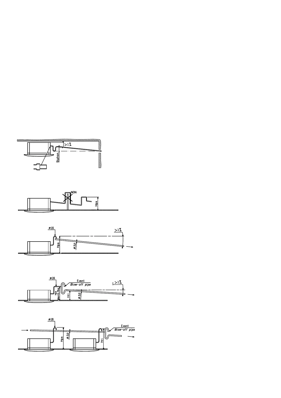
Une pente de 1 % sera réalisée sur le tube
d’évacuation des condensats, toute remontée
sera à éviter absolument. La hauteur maxi de
relevage de la pompe est de Hps maxi = 0,75 m
avec un tube de Ø 16 mm ; pour un tube de Ø 32
mm, remontée maximum Hps = 0.4 m
En cas de contre-pression sur la tuyauterie
d’évacuation des condensats, il y a lieu de pré-
voir un siphon et un évent conformément aux
figures ci-après.
The condensates collected in the recovery tank
run into a water reserve equipped with:
an evacuation pump
a safety float that stops the unit if there is a
problem with condensate evacuation (pump
faulty, obstruction of evacuation pipe, etc.)
The condensates shall preferably be evacuated
through the insulated 32-mm dia. rigid PVC
pipe. This pipe will be connected directly onto
the female evacuation union (PVC) of the unit.
The condensates evacuation tube shall be
given a downward gradient of 1%; it is essential
to avoid the tube having an upward gradient.
The maximum height of lift of the pump is Hps
max = 0.75 m with a 16-mm dia. tube; with a
32-mm dia. tube the maximum Hps = 0.4 m
In case of back-pressure in the condensates
evacuation pump, a trap and blow off pipe must
be provided as shown in the figures below.
∅
∅
∅
Installation :
Pour assurer le bon
écoulement, prévoir
une pente régulière
minimum de 1 % sur le
tube d’évacuation Ø 32
Prévoir un siphon pour
empêcher les mauvai-
ses odeurs de se pro-
pager dans la pièce.
Installation
:
To ensure good flow,
give the 32-mm dia.
evacuation tube a regu-
lar donward gradient of
1% minimum.
Provide a trap to pre-
vent unpleasant smells
from circulating in the
room
Ø
Montage simple avec
relevage en tête de
conduite.
Lorsqu’il est néces-
saire de vidanger les
condensats à un
niveau supérieur de la
cassette, prévoir un
tuyau rigide ou souple
de Ø 16 mm extérieur.
Ce montage évite l’en-
clenchement intem-
pestif du flotteur de
sécurité en cas d’arrêt
de la cassette.
Simple setup with rai-
sing of tube at head.
When the condensates
have to be drained at a
level higher than the
unit, provide a rigid or
flexible pipe of 16-mm
outside diameter. This
setup prevents unti-
mely triggering of the
safety float if the air
conditioning unit stops.
Ø
En cas de contre-pres-
sion prévoir un évent tel
que : Hps - Hri > sur-
pression admissible du
réseau.
In the event of back-
pressure, provide a
blow off pipe such that:
Hps - Hri > permissible
system overpressure.
Montage simple avec
relevage en bout de
conduite.
Pour une installation
avec plusieurs casset-
tes, système d’évacua-
tion avec plusieurs
communs avec une
éventuelle contre-pres-
sion < Hps - Hri.
Le collecteur principal
doit être dimensionné
de manière à permettre
l’écoulement simultané
de condensats de tou-
tes les cassettes.
Simple setup with rai-
sing at end of duct.
With a system compri-
sing several units, an
evacuation system
with several commons
and, if applicable, back-
pressure
< Hps - Hri.
The main manifold
must be dimensioned
to allow the simulta-
neous flow of conden-
sates from all the units.
 Loading...