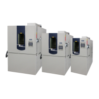
GENERAL DESCRIPTION
31
Bypass Loop (R23 Systems 3.5 HP – 15 HP)
The discharge refrigerant vapor passes a tee, where some of the vapor is diverted to the suction line.
The discharge vapor passes through the hot gas bypass solenoid (item 262), and through a hot gas
bypass regulator valve (item 263). The hot gas bypass solenoid valve (item 262) will open and close
opposite of the liquid line solenoid valve (item 210). The hot gas bypass regulator valve will allow hot
discharge refrigerant vapor to flow directly to the suction line. This is done as a means to control
cooling capacity or to “unload” the system. The liquid injection thermostatic expansion valve (item
261) will sense the temperature of the suction gas and automatically open to feed liquid refrigerant
into the suction line. This will provide cooling for the hot gas that is being fed into the suction line.
The cooling effect keeps the compressor from overheating. These systems also come equipped with a
discharge temperature control loop. The control loop consists of a liquid solenoid valve (item 277)
and a discharge temperature control valve (item 278). The liquid line solenoid is energized when the
compressor is running.
Bypass Loop (R23 Systems 20 HP)
The discharge refrigerant vapor passes a tee where some of the vapor is diverted to the suction line.
The discharge vapor passes through the hot gas bypass solenoid (item 262), and through a hot gas
bypass regulator valve (item 263). The hot gas bypass solenoid valve (item 262) will open and close
opposite of the liquid line solenoid valve (item 210). The hot gas bypass regulator valve will allow hot
discharge refrigerant vapor to flow directly to the suction line. This is done as a means to control
cooling capacity or to “unload” the system. The liquid injection thermostatic expansion valve (item
261) will sense the temperature of the suction gas and automatically open to feed liquid refrigerant
into the suction line. This will provide cooling for the hot gas that is being fed into the suction line.
The cooling effect keeps the compressor from overheating. These systems also come equipped with a
discharge temperature control loop. The control loop consists of a liquid solenoid valve (item 277),
and a hand expansion valve (item 278). This valve is set at the factory. The liquid line solenoid is
controlled by a discharge temperature monitor and will open at a factory preset temperature.
CASCADE CONTROL SYSTEM
(Refer to Refrigeration Diagram in Drawing Section)
Mode: Normal cooling/heating (2 HP – 3.5 HP)
When there is a call for cooling, the R-508B/R-23 liquid line solenoid (202-SOL) and the R-404A
compressor turns on. Thirty seconds later, the R-508B/R-23 compressor turns on. The high pressure
switch (101-PS and 204-PS) will turn the compressor off if a high discharge pressure event is reached.
Contact Cincinnati Sub-Zero’s service department if this occurs. The high pressure switch will
automatically reset. When there is call for cooling, (202-SOL) is energized. When the chamber is near
the set point, the controller begins to cycle (202-SOL) on and off. If the chamber does not call for
cooling for ninety seconds, the refrigeration system will turn off.
When there is a call for heating, (202-SOL) will deenergize, and the heaters will energize.