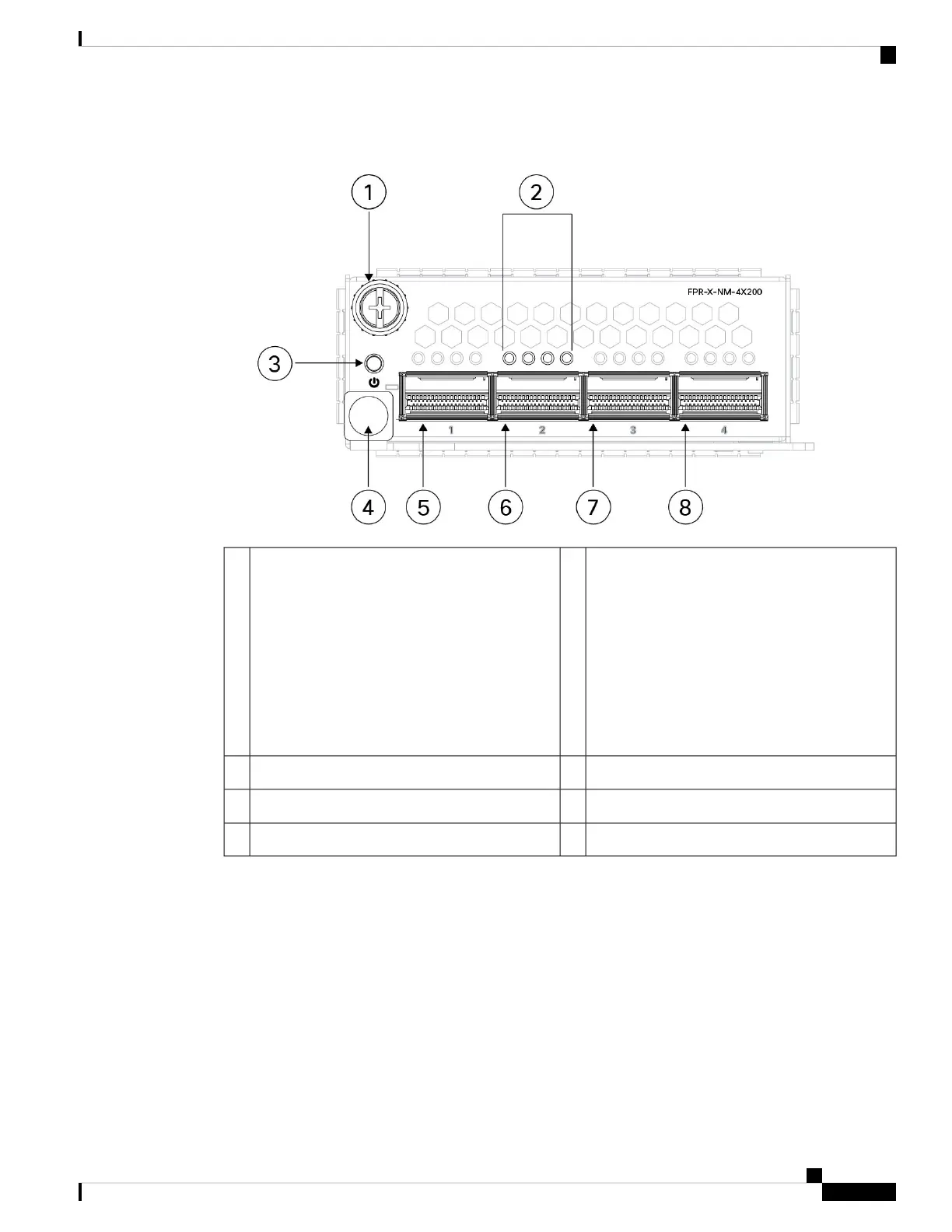
Figure 11: 4-Port 200-Gb Network Module (FPR-X-NM-4X200G)
Network activity LEDs
The up arrows represent the top ports and the
down arrows represent the bottom ports.
• Off—No SFP.
• Amber—No link or a network failure.
• Green—Link is up.
• Green, flashing—Network activity.
2Captive screw1
Ejector handle4Power on LED3
Ethernet 2/2 or 3/26Ethernet 2/1 or 3/15
Ethernet 2/4 or 3/48Ethernet 2/3 or 3/37
For More Information
• See 8-Port 1/10/25-Gb Network Module, on page 15 for a description of the 8-port 1/10/25-Gb
network module.
• See 8-Port 1000Base-T Network Module with Hardware Bypass, on page 22 for a description of
the 8-port 10/100/1000Base-T network module.
• See Install, Remove, and Replace the Network Module, on page 63 for the procedure for removing
and replacing network modules.
Cisco Secure Firewall 4200 Series Hardware Installation Guide
21
Overview
4-Port 200-Gb Network Module
 Loading...