6-67
Hardware Installation Guide for Cisco 4000 Series Integrated Services Routers
OL-32185-02
Chapter 6 Install and Upgrade Internal Modules and FRUs
Remove and Install the Flash Memory Card
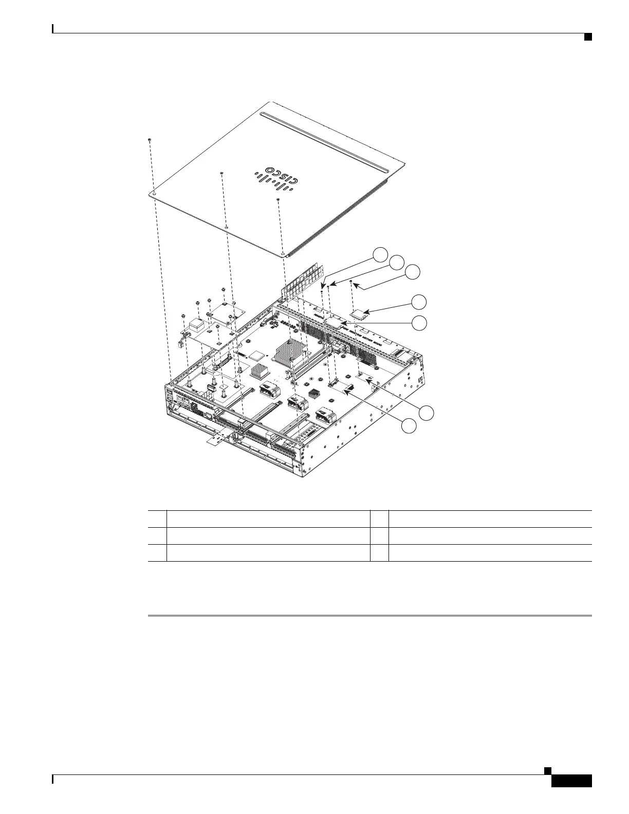
Figure 6-48 Memory Cards
Step 4
Tighten the supplied screw (see Figure 6-48) to secure the flash memory card in place.
Step 5 Replace the chassis cover. See “Remove and Replace the Chassis Cover” section on page 6-4.
1 Supplied screw 2 Supplied screw
3 Flash memory card 4 SSD mSATA storage device
5 Flash memory card connector 6 SSD mSATA connector