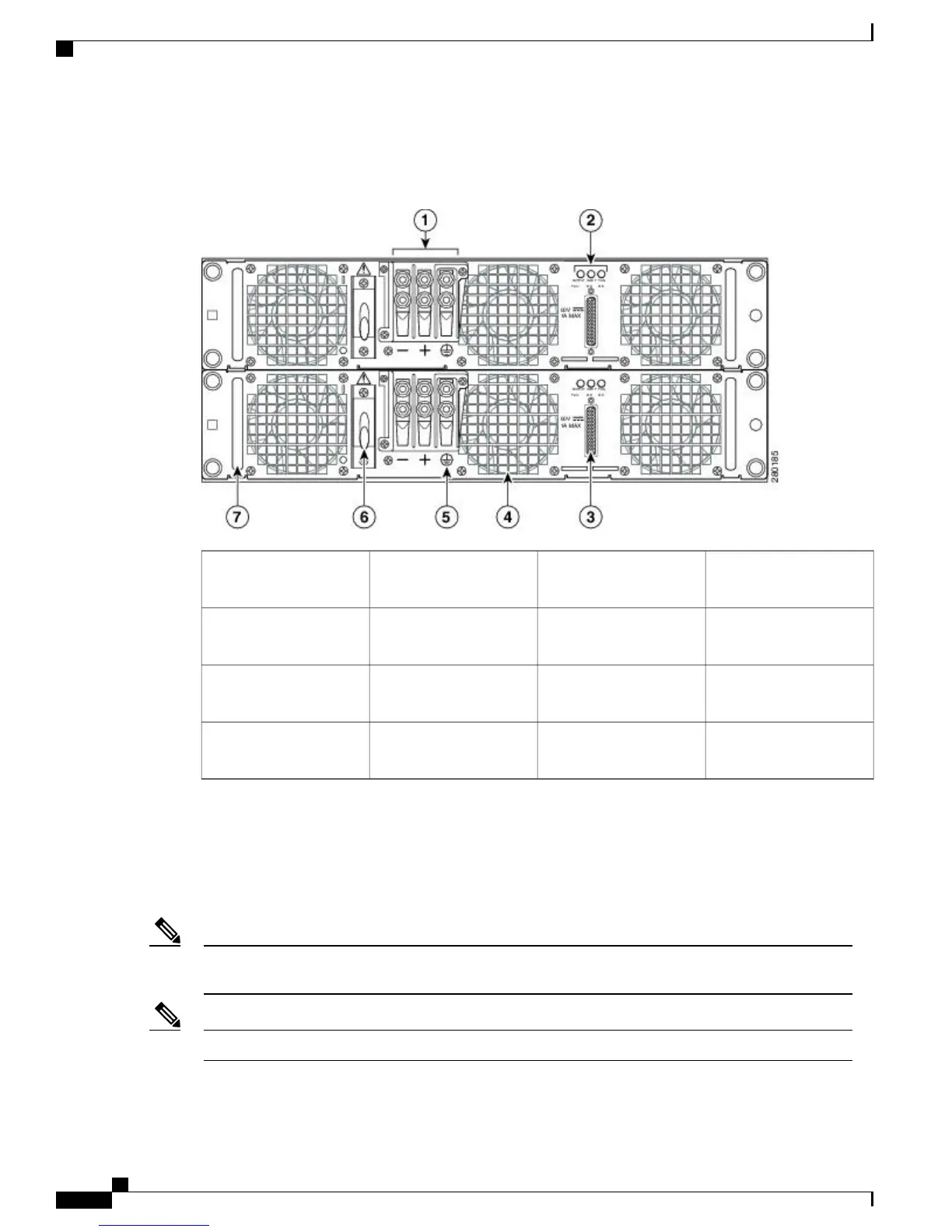
The following image shows the rear of the Cisco ASR 1004 Router with two –48 VDC power supplies installed.
Figure 3: Cisco ASR 1004 Router Rear View With
–
48 VDC Power Supplies
Grounding symbol5
–48 VDC power supply
terminal block
1
–48 VDC power supply
On/Off switch
6
–48 VDC power supply
LEDs
2
–48 VDC power supply
handle
7
–48 VDC power supply
DB-25 alarm connector
3
——–48 VDC power supply
fan
4
Internal fans draw cooling air into the chassis and across internal components to maintain an acceptable
operating temperature. (See Figure 2: Cisco ASR 1004 Router Rear View with AC Power Supplies, on page
3.) The fans are located at the rear of the chassis. A two-hole grounding lug is located on the side of the
chassis. Two power supplies, either two AC power supplies or two –48 VDC power supplies, are accessed
from the rear of the router.
You have already unpacked your chassis and read all the site requirements for your new equipment.
Proceed with the installation.
Note
Do not combine AC and –48 VDC power supplies in the same chassis.
Note
Cisco ASR 1000 Series Router Hardware Installation Guide
4
Cisco ASR 1004 Router Overview and Installation
Rear View
 Loading...


