the wire. Stripping more than the recommended amount of wire can leave behind exposed wire from the terminal block
after installation.
Step 4
Prepare the cables by attaching the lugs to the cables.
Step 5
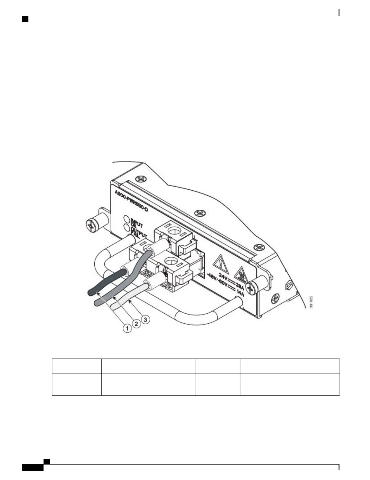
Identify the ground, positive, and negative feed positions for the terminal block connection (see the figure below). The
recommended wiring sequence is:
•
Negative (-) lead wire (top)
•
Ground lead wire (left)
•
Positive (+) lead wire (right)
Figure 68: DC Power Supply Terminal Block Plug in the Block Header
DC power supply positive (+) lead wire3DC power supply ground lead wire1
—
DC power supply negative (-) lead
wire
2
Step 6
Insert the lugged end of the cables to the connector and secure the cables using the captive screws.
Cisco ASR 903 Aggregation Services Router Hardware Installation Guide
110
Installing the Cisco ASR 903 Router
Installing the DC Power Supply

 Loading...


