When installing the cabling to the RSPs, we recommend that you leave a service loop of extra
cabling sufficient to allow for fan tray removal.
Note
Step 3 Secure the fan tray to the chassis using the attached captive installation screws. The recommended maximum
torque is 5.5 in.-lb (.62 N-m).
This completes the procedure for installing or replacing the fan tray in a Cisco ASR 907 Router.
For a video walk-through of these instructions, see
http://www.cisco.com/c/en/us/td/docs/routers/asr907/hardware/video/asr907-fantray.html.
For information about connecting cables to the fan tray alarm port, see Connecting the Fan Tray Alarm Port.
For a summary of the LEDs on the fan tray, see LED Summary. For more information about air flow guidelines,
see Air Flow Guidelines.
Removing and Replacing the Dust Filter
The chassis is shipped with a blank fan filter cover. To install the dust filter:
Procedure
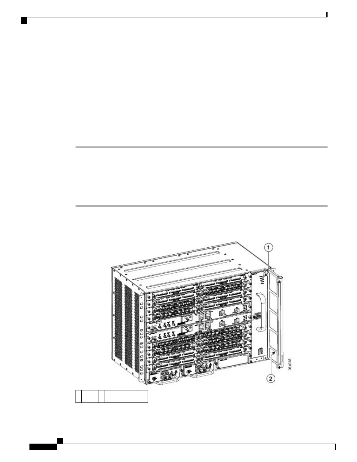
Step 1 Remove the blank fan filter cover (A907-FAN-F=) by unscrewing the captive installation screws at the top
and bottom of the dust filter frame. See the figure below.
Figure 17: Blank Fan Filter
Dummy fan filter2LEDs1
Installing the Cisco ASR 907 Router
16
Installing the Cisco ASR 907 Router
Removing and Replacing the Dust Filter
 Loading...


