Figure 31: T1/E1 Cable Connector
16 x T1/E1 Cable Connectors
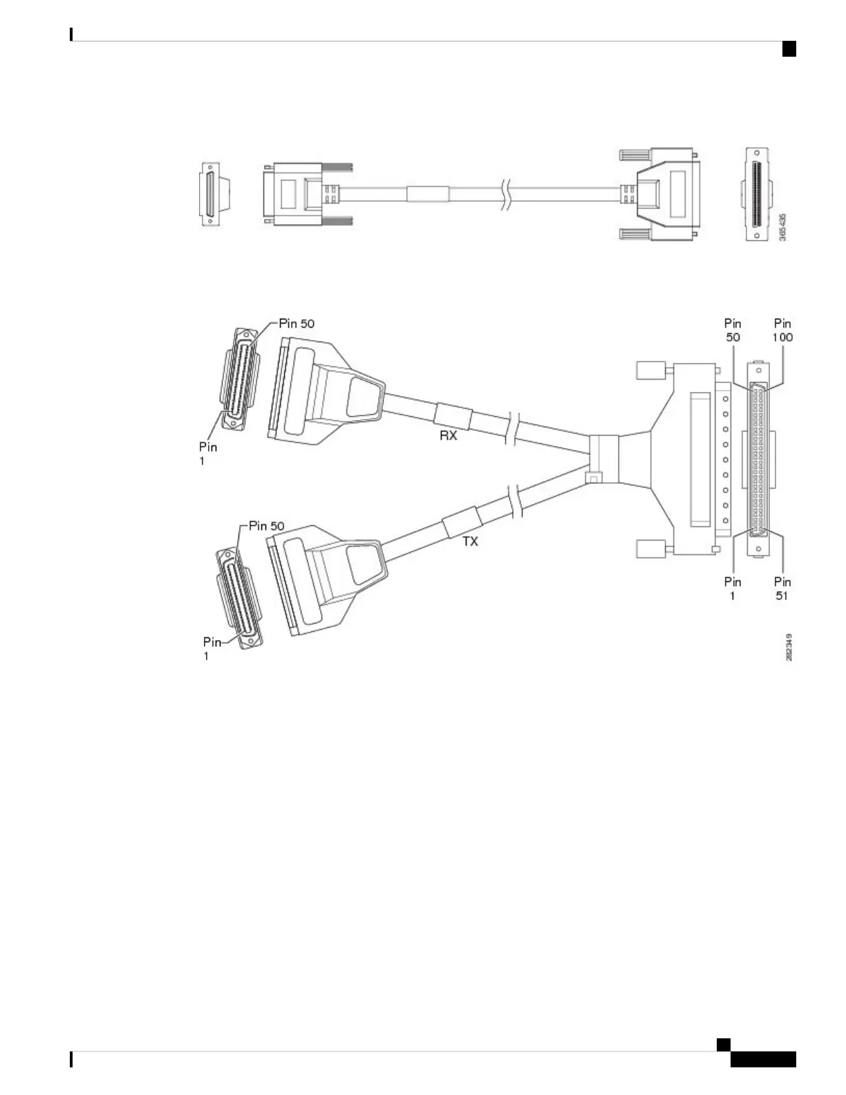
Figure 32: 16 x T1/E1 Cable Connector
One end of the cable (see the figure above) has a 100-pin connector that plugs into the T1/E1 interface module.
Use the thumbscrews on either side of the connector to secure the cable to the interface.
The other end of the cable has two 50-pin Telco connectors that attach to the rear of a 24-port RJ45 patch
panel. Both connectors are identical: one is for Transmit (TX) and the other is for Receive (RX).
The figure below shows how the cable is connected between the 16 x T1/E1 interface module and the patch
panel.
Installing the Cisco ASR 907 Router
53
Installing the Cisco ASR 907 Router
16 x T1/E1 Cable Connectors
 Loading...


