Chapter 2 Installing and Starting the Switch
Installing the Switch
2-20
Catalyst 3550 Multilayer Switch Hardware Installation Guide
78-11358-03
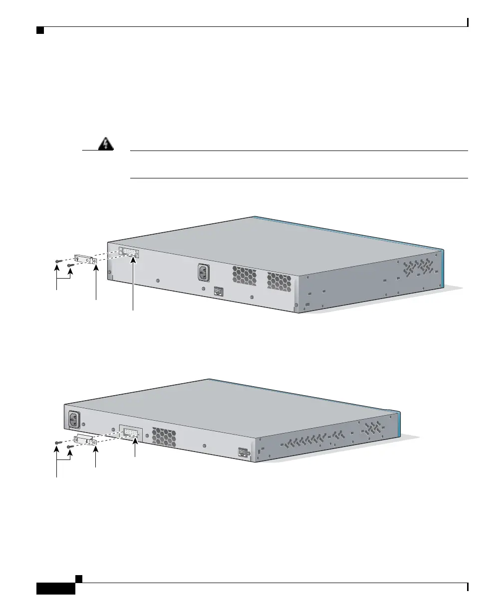
Attaching the RPS Connector Cover
If you are not using an RPS with your switch, use the two Phillips pan-head
screws to attach the RPS connector cover to the back of the switch, as shown in
Figure 2-18 and Figure 2-19.
Warning
If an RPS is not connected to the switch, install an RPS connector cover on the
back of the switch.
Figure 2-18 Attaching the RPS Connector Cover on the Catalyst 3550-12T and 3550-12G Switches
Figure 2-19 Attaching the RPS Connector Cover on the Catalyst 3550-24, 3550-48, or 3550-24-FX
Switches
100-240V~
5-3A
50/60Hz
DC OUTPUT 1
C
O
N
SO
LE
60966
Phillips
pan-head
screws
RPS
connector
cover
RPS
connector
100-240V~
5-3A
50/60Hz
DC OUTPUT 1
C
O
N
SO
LE
60964
Phillips
pan-head
screws
RPS
connector
cover
RPS
connector
 Loading...


