2-41
Catalyst 3550 Multilayer Switch Hardware Installation Guide
78-11358-03
Chapter 2 Installing and Starting the Switch
Connecting a PC or Terminal to the Console Port
Follow these steps to connect the PC or terminal to the switch:
Step 1 Configure the baud rate and character format of the PC or terminal to match these
console port default characteristics:
• 9600 baud
• 8 data bits
• 1 stop bit
• No parity
After you have gained access to the switch, you can change the console baud rate
through the Administration > Console Baud Rate menu in the Cluster
Management Suite (CMS).
Step 2 Using the supplied RJ-45-to-DB-9 adapter cable, insert the RJ-45 connector into
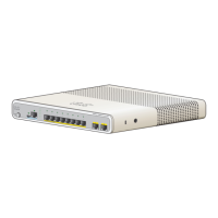
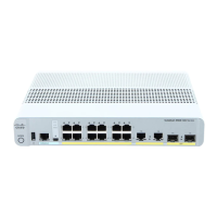
the console port, as shown in Figure 2-39 and Figure 2-40.
Step 3 Attach the DB-9 female DTE adapter of the RJ-45-to-DB-9 adapter cable to a PC,
or attach an appropriate adapter to the terminal.
Step 4 Start the terminal-emulation program if you are using a PC or terminal.
Figure 2-39 Connecting to the Catalyst 3550-12T and 3550-12G Console Port
1
0
0-2
4
0
V
~
5
-3
A
5
0
/6
0
H
z
CO
NSO
LE
RJ-45
console
port
74427
 Loading...


