Large Cable Rubber Gland 0.30 to 0.50 inch (7.6
to 12.7 mm) diameter
6Duplex LC Fiber-optic cable2
Small Cable Rubber Gland 0.24 to 0.30 inch (6.0
to 7.6 mm) diameter
7SFP Gland Adapter body3
Gland nut8Body O-ring4
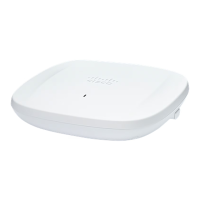
Step 5 Terminate the SC or LC fiber optic cable.
Figure 85: SC Fiber-optic cable
Optic fiber cable2SC optic fiber connector1
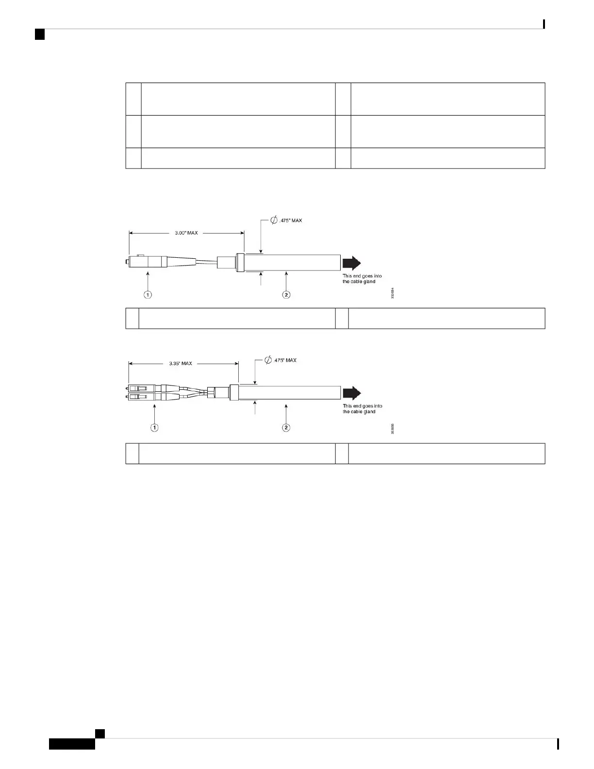
Figure 86: Duplex LC Fiber Optic Cable
Optic fiber cable2Duplex LC optic fiber connector1
Step 6 Using caution not to damage the fiber connector end, pass the fiber connector through the adapter gland
components. Ensure components are ordered and orientated, as shown in Figure 86: Duplex LC Fiber Optic
Cable, on page 78.
Ensure you use the proper rubber gland combination. If the fiber cable outside diameter (OD) is
0.30 to 0.50 inches (7.6 to 12.7 mm), then the small rubber gland can be discarded. If the cable OD
is 0.24 to 0.30 inches (6.0 to 7.6 mm), then the small rubber gland is inserted into the large rubber
gland.
Note
Step 7 Verify the O-ring is correctly seated on the gland adapter body. Re-assemble the components of the adapter
gland. Do not tighten the gland nut on the rubber inserts. Leave it loose so the gland can easily slide on the
fiber cable. If you tightened the cable in this step, you might damage the cable.
Step 8 Insert the SC or LC optic fiber connector-end of the cable into the SFP transceiver module and ensure it latches
into place.
Step 9 Thread the adapter body into the SFP port on the AP. Tighten the adapter body by hand until it is fully seated.
Inspect that the body is seated correctly. Using an adjustable wrench, tighten the body snugly to the AP body
to approximately 13 to 17 lb-in (15 to 20 kgf-cm) of torque.
Cisco Catalyst 9124AX Series Outdoor Access Point Hardware Installation Guide
78
Installation Overview
Connecting a Fiber-optic Cable to the AP (AIR-SFP-KIT1=)