EasyManuals Logo

Cisco Catalyst 9200 Series Installation Guide

Cisco Catalyst 9200 Series
90 pages
To Next Page IconTo Next Page
To Previous Page IconTo Previous Page
Page #25 background imageLoading...
Page #25 background image
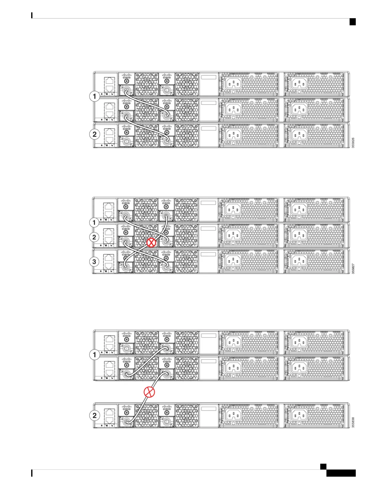
Figure 12: Example of a Data Stack with Half Bandwidth Connections
The figures below show data stacks of switches with failover conditions. In this figure, the StackWise cable
is bad in link 2. Therefore, this stack provides only half bandwidth and does not have redundant connections.
Figure 13: Example of a Data Stack with a Failover Condition
In this figure, link 2 is bad. Therefore, this stack partitions into two stacks, and the top and bottom switches
become the active switch in the stack. If the bottom switch is a member (not active or standby switch), it
reloads.
Figure 14: Example of a Partitioned Data Stack with a Failover Condition
Cisco Catalyst 9200 Series Switches Hardware Installation Guide
19
Installing the Switch
Data Stack Bandwidth and Partitioning Examples

Table of Contents

Other manuals for Cisco Catalyst 9200 Series

Questions and Answers:

Question and Answer IconNeed help?

Do you have a question about the Cisco Catalyst 9200 Series and is the answer not in the manual?

Cisco Catalyst 9200 Series Specifications

General IconGeneral
CategorySwitch
Stacking Bandwidth160 Gbps
LayerLayer 2 and Layer 3
Operating SystemCisco IOS XE
Operating Temperature0°C to 45°C (32°F to 113°F)
SeriesCisco Catalyst 9200 Series
Ports24 or 48 Ethernet ports
Switching CapacityUp to 176 Gbps
PoEPoE, PoE+, and UPOE
StackingStackWise-160
Memory4 GB DRAM, 4 GB Flash
Network ManagementCisco DNA Center, WebUI, CLI
Security Features802.1X, TrustSec, MACsec
WarrantyLimited Lifetime Warranty
Dimensions1.73 x 17.5 x 11.3 in. (4.4 x 44.5 x 28.8 cm)

Related product manuals