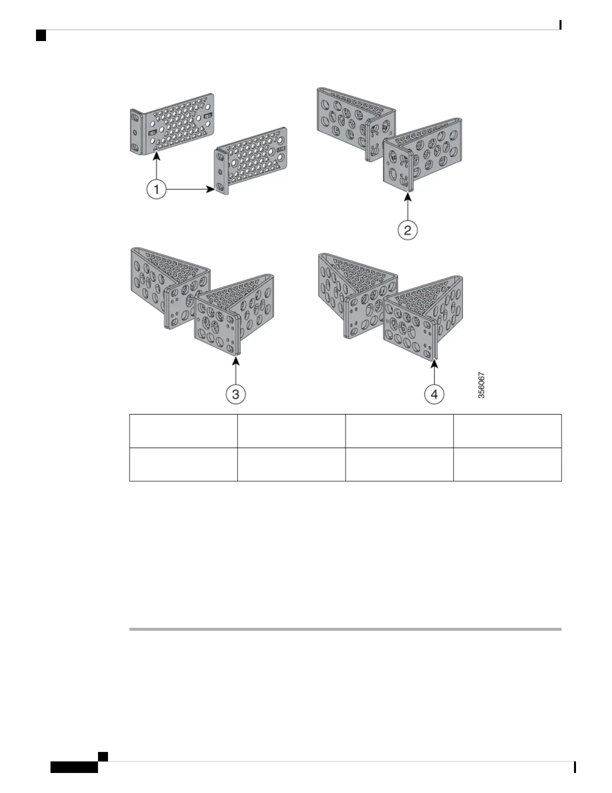
EasyManuals Logo

Cisco Catalyst 9200 Series Installation Guide

Cisco Catalyst 9200 Series
90 pages
To Next Page IconTo Next Page
To Previous Page IconTo Previous Page
Page #28 background imageLoading...
Page #28 background image
23-inch brackets
(RACK-KIT-T1=)
319-inch brackets
(RACK-KIT-T1=)
1
24-inch brackets
(RACK-KIT-T1=)
4ETSI brackets
(RACK-KIT-T1=)
2
Attaching the Rack-Mount Brackets
Before you begin
You can use the minimum recommended number of two screws for installing the rack-mount bracket to each
side of the switch. If required, while mounting, you can use the additional four screws provided in the accessory
kit.
Procedure
Use two Phillips flat-head screws to attach the long side of the bracket to each side of the switch for the front-
or rear-mounting positions.
The following illustration shows a C9200L switch. C9200 switches follow the same method for installing the
rack mount bracket.
Cisco Catalyst 9200 Series Switches Hardware Installation Guide
22
Installing the Switch
Attaching the Rack-Mount Brackets

Table of Contents

Other manuals for Cisco Catalyst 9200 Series

Questions and Answers:

Question and Answer IconNeed help?

Do you have a question about the Cisco Catalyst 9200 Series and is the answer not in the manual?

Cisco Catalyst 9200 Series Specifications

General IconGeneral
CategorySwitch
Stacking Bandwidth160 Gbps
LayerLayer 2 and Layer 3
Operating SystemCisco IOS XE
Operating Temperature0°C to 45°C (32°F to 113°F)
SeriesCisco Catalyst 9200 Series
Ports24 or 48 Ethernet ports
Switching CapacityUp to 176 Gbps
PoEPoE, PoE+, and UPOE
StackingStackWise-160
Memory4 GB DRAM, 4 GB Flash
Network ManagementCisco DNA Center, WebUI, CLI
Security Features802.1X, TrustSec, MACsec
WarrantyLimited Lifetime Warranty
Dimensions1.73 x 17.5 x 11.3 in. (4.4 x 44.5 x 28.8 cm)

Related product manuals