EasyManuals Logo

Cisco Catalyst 9200 Series Installation Guide

Cisco Catalyst 9200 Series
90 pages
To Next Page IconTo Next Page
To Previous Page IconTo Previous Page
Page #83 background imageLoading...
Page #83 background image
STACK LED
The STACK LED shows the sequence of member switches in a stack. Up to eight switches can be members
of a stack. The first eight port LEDs show the member number of a switch in a stack.
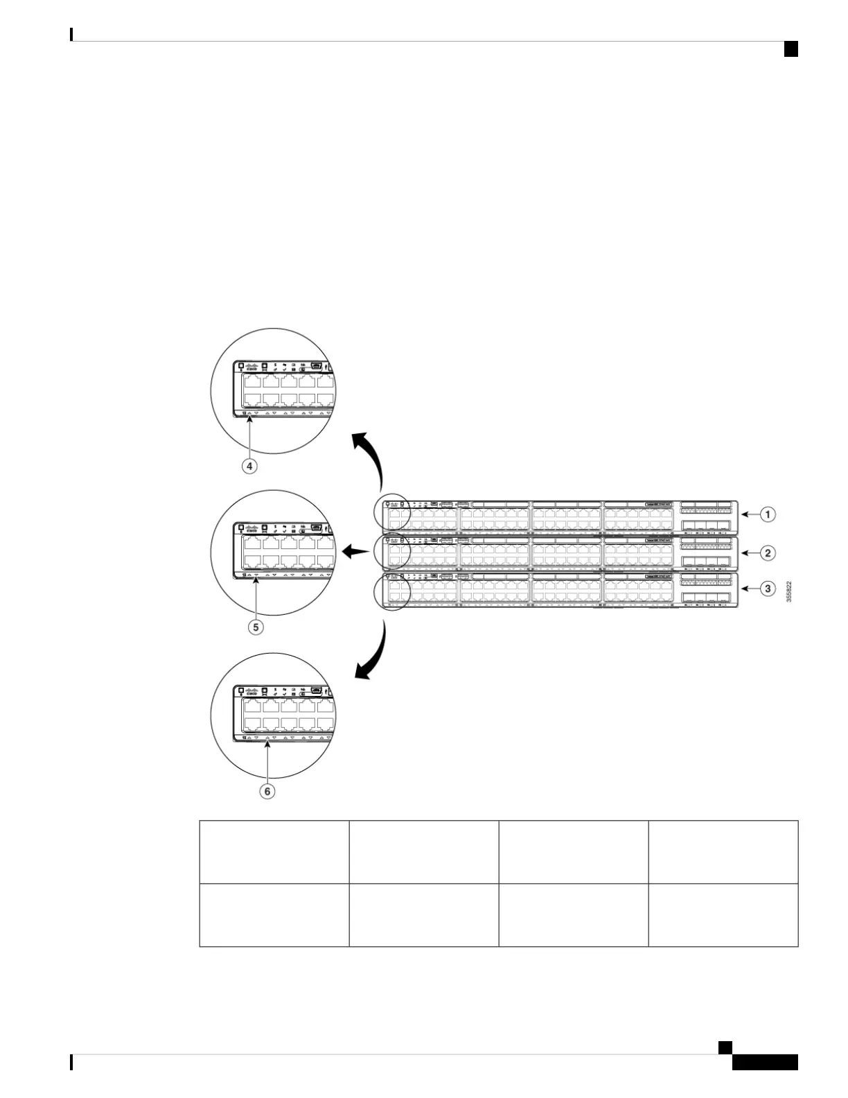
Figure 47: STACK LED
This figure shows the LEDs on for each switch. When you press the Mode button to select the STACK LED,
the corresponding port LEDs will blink green for each switch. For example, for switch 1, port 1 will blink
green and the rest of the LEDs will be off. On switch 2, port 2 will blink green and the rest of the LEDs will
be off. The same behavior will be seen with the remaining switches in the stack.
LED blinks green to show
that this is switch 1 in the
stack.
4Stack member 11
LED blinks green to show
that this is switch 2 in the
stack.
5Stack member 22
Cisco Catalyst 9200 Series Switches Hardware Installation Guide
77
Switch LEDs
STACK LED

Table of Contents

Other manuals for Cisco Catalyst 9200 Series

Questions and Answers:

Question and Answer IconNeed help?

Do you have a question about the Cisco Catalyst 9200 Series and is the answer not in the manual?

Cisco Catalyst 9200 Series Specifications

General IconGeneral
CategorySwitch
Stacking Bandwidth160 Gbps
LayerLayer 2 and Layer 3
Operating SystemCisco IOS XE
Operating Temperature0°C to 45°C (32°F to 113°F)
SeriesCisco Catalyst 9200 Series
Ports24 or 48 Ethernet ports
Switching CapacityUp to 176 Gbps
PoEPoE, PoE+, and UPOE
StackingStackWise-160
Memory4 GB DRAM, 4 GB Flash
Network ManagementCisco DNA Center, WebUI, CLI
Security Features802.1X, TrustSec, MACsec
WarrantyLimited Lifetime Warranty
Dimensions1.73 x 17.5 x 11.3 in. (4.4 x 44.5 x 28.8 cm)

Related product manuals