EasyManuals Logo

Cisco Catalyst 9400 Series User Manual

Cisco Catalyst 9400 Series
192 pages
To Next Page IconTo Next Page
To Previous Page IconTo Previous Page
Page #109 background imageLoading...
Page #109 background image
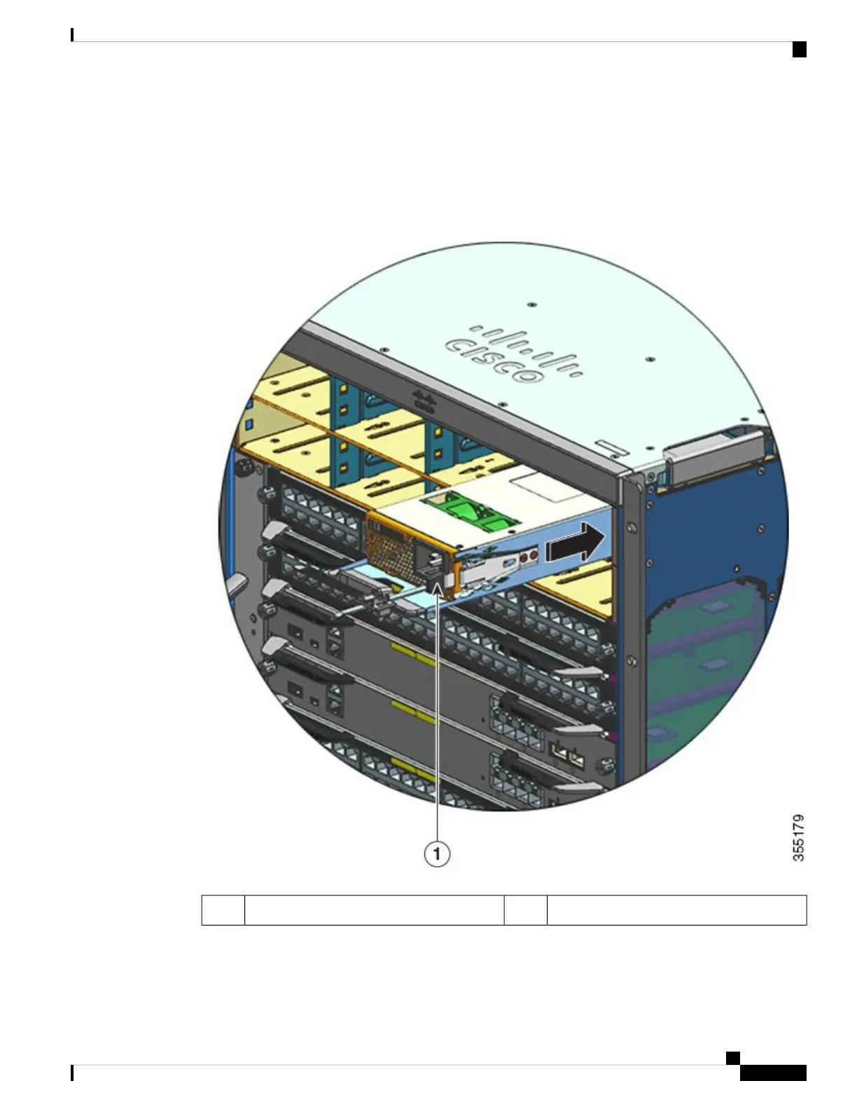
Step 4 Grasp the power supply handle with one hand and place your other hand underneath to support the bottom of
the power supply. Slide the power supply all the way into the power supply bay. Make sure that the power
supply is fully seated in the bay.
When correctly installed, the latch on the power supply locks-in the module, to avoid accidental removal of
the module.
--Power supply latch, which clicks into place1
Step 5 Verify that all site power and grounding requirements have been met.
Cisco Catalyst 9400 Series Switches Hardware Installation Guide
103
Removing and Replacing FRUs
Installing an AC-Input Power Supply Module

Table of Contents

Other manuals for Cisco Catalyst 9400 Series

Questions and Answers:

Question and Answer IconNeed help?

Do you have a question about the Cisco Catalyst 9400 Series and is the answer not in the manual?

Cisco Catalyst 9400 Series Specifications

General IconGeneral
SeriesCatalyst 9400 Series
Form FactorRack-mountable
Operating SystemCisco IOS XE
Uplink Options40G and 100G uplinks
StackingNot supported
Layer SupportLayer 2 and Layer 3
Operating Temperature0°C to 40°C (32°F to 104°F)
Storage Temperature-40°C to 70°C (-40°F to 158°F)
Humidity5% to 90% noncondensing
Power Supply OptionsAC and DC power supplies
RedundancyPower supply, supervisor engine
Modular Slots7 or 10
MAC Address Table Size256, 000
Security FeaturesACLs, TrustSec, MACsec
ManagementCLI, SNMP, NETCONF, RESTCONF, Cisco DNA Center

Related product manuals