EasyManuals Logo

Cisco Catalyst 9400 Series User Manual

Cisco Catalyst 9400 Series
192 pages
To Next Page IconTo Next Page
To Previous Page IconTo Previous Page
Page #121 background imageLoading...
Page #121 background image
Step 3 Close the terminal block cover and finger-tighten the captive installation screw (approximately 0.25 Nm).
Removing a DC-Input Power Supply Module from the Chassis
To remove a DC-input power supply module from the chassis, follow the steps described here.
Before you begin
Only trained and qualified personnel should be allowed to install, replace, or service this equipment. Statement
1030
Warning
No user-serviceable parts inside. Do not open. Statement 1073
Warning
Procedure
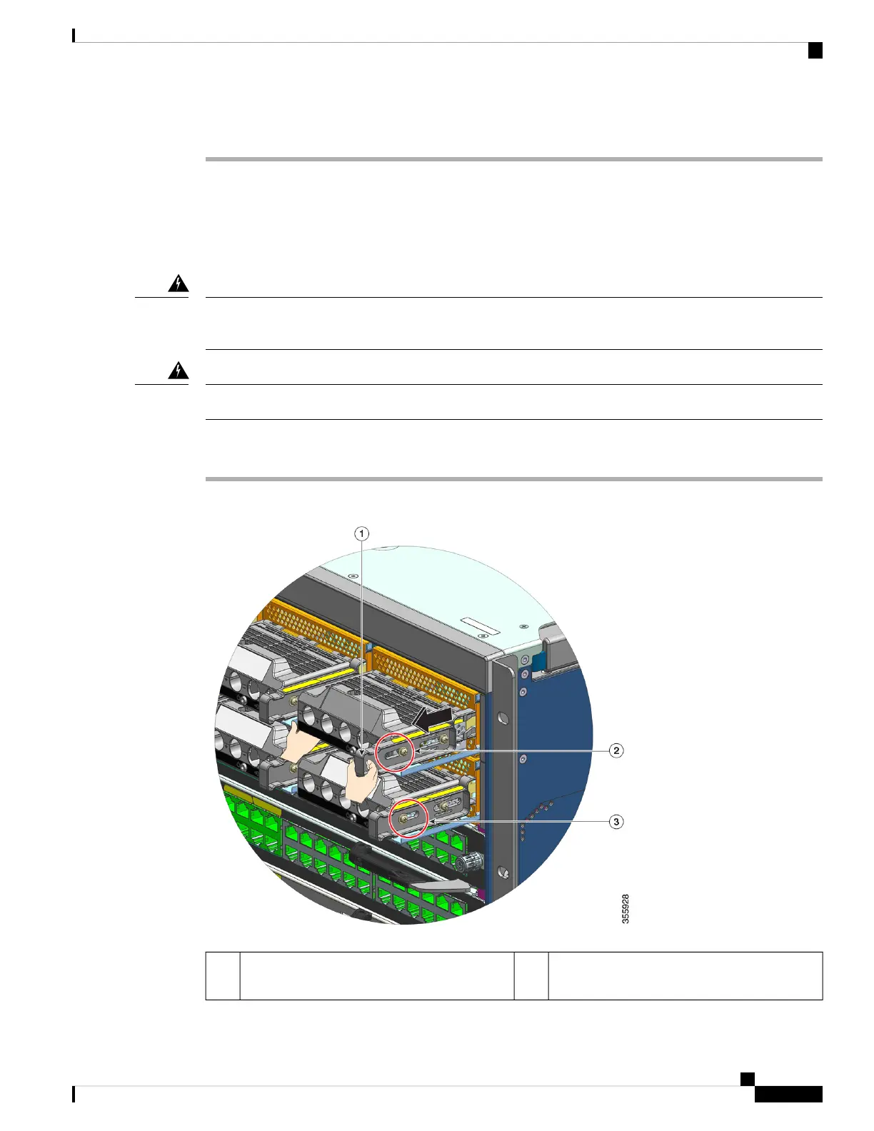
Step 1 Pull out the latch on the module, to unlock it.
Comparative location of the nut on a module
where the release latch has not been pulled out.
3Release latch to be pulled out (towards yourself)1
Cisco Catalyst 9400 Series Switches Hardware Installation Guide
115
Removing and Replacing FRUs
Removing a DC-Input Power Supply Module from the Chassis

Table of Contents

Other manuals for Cisco Catalyst 9400 Series

Questions and Answers:

Question and Answer IconNeed help?

Do you have a question about the Cisco Catalyst 9400 Series and is the answer not in the manual?

Cisco Catalyst 9400 Series Specifications

General IconGeneral
SeriesCatalyst 9400 Series
Form FactorRack-mountable
Operating SystemCisco IOS XE
Uplink Options40G and 100G uplinks
StackingNot supported
Layer SupportLayer 2 and Layer 3
Operating Temperature0°C to 40°C (32°F to 104°F)
Storage Temperature-40°C to 70°C (-40°F to 158°F)
Humidity5% to 90% noncondensing
Power Supply OptionsAC and DC power supplies
RedundancyPower supply, supervisor engine
Modular Slots7 or 10
MAC Address Table Size256, 000
Security FeaturesACLs, TrustSec, MACsec
ManagementCLI, SNMP, NETCONF, RESTCONF, Cisco DNA Center

Related product manuals