EasyManuals Logo

Cisco Catalyst 9400 Series User Manual

Cisco Catalyst 9400 Series
192 pages
To Next Page IconTo Next Page
To Previous Page IconTo Previous Page
Page #122 background imageLoading...
Page #122 background image
--Location of the nut on the side when the release
latch has been pulled
2
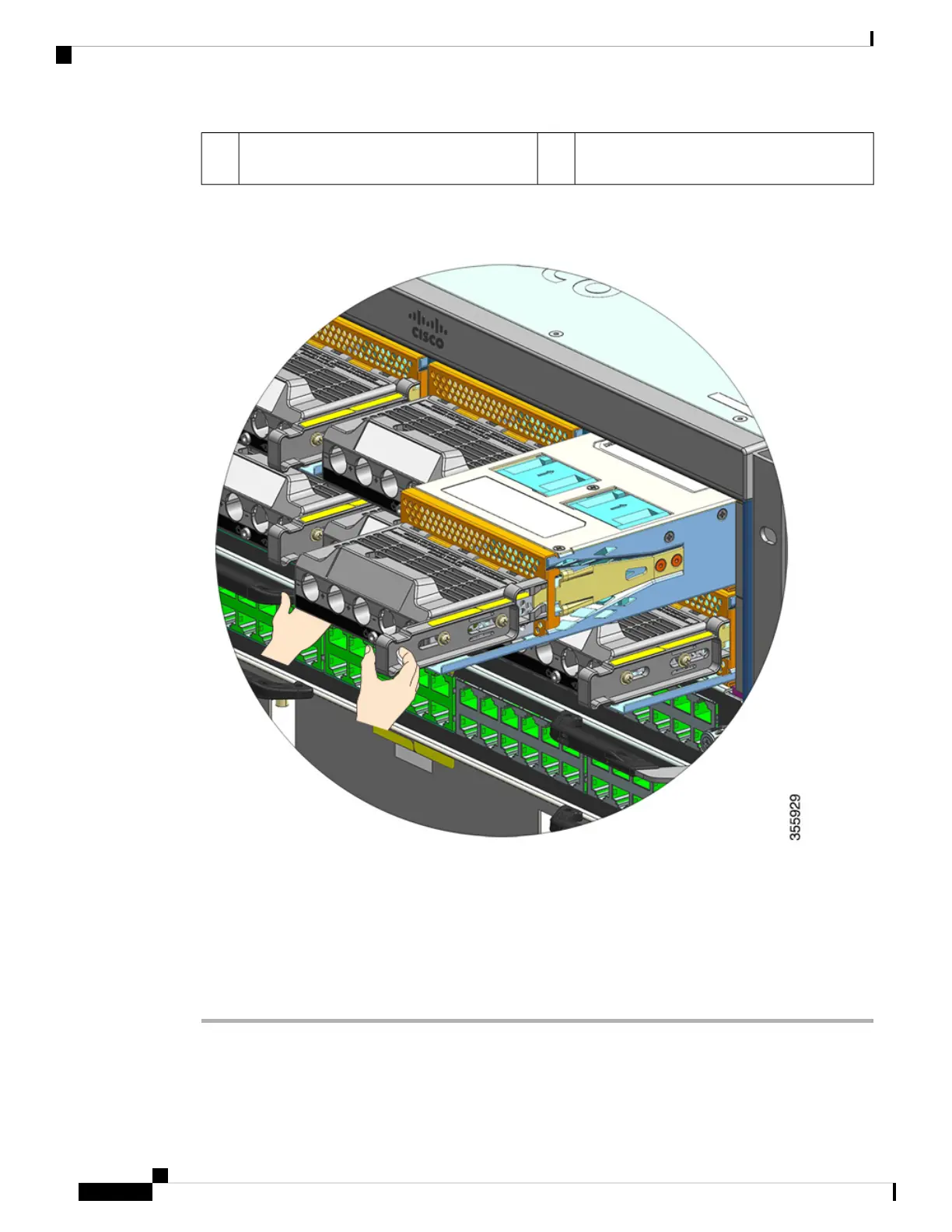
Step 2 Grasp the terminal block with one hand and place your other hand underneath as you slide the power supply
module out of the bay.
Step 3 Install another power supply module. If you are not going to install another module, you must install a blank
cover (C9400-PWR-BLANK) to maintain proper airflow through the chassis.
Do not leave any power supply slot open for any amount of time while the system is powered up.
Prior to inserting a new power supply unit, for instance, when you are replacing a unit, ensure there
are no foreign, conductive, or other objects, or debris in the slot.
Caution
Cisco Catalyst 9400 Series Switches Hardware Installation Guide
116
Removing and Replacing FRUs
Removing a DC-Input Power Supply Module from the Chassis

Table of Contents

Other manuals for Cisco Catalyst 9400 Series

Questions and Answers:

Question and Answer IconNeed help?

Do you have a question about the Cisco Catalyst 9400 Series and is the answer not in the manual?

Cisco Catalyst 9400 Series Specifications

General IconGeneral
SeriesCatalyst 9400 Series
Form FactorRack-mountable
Operating SystemCisco IOS XE
Uplink Options40G and 100G uplinks
StackingNot supported
Layer SupportLayer 2 and Layer 3
Operating Temperature0°C to 40°C (32°F to 104°F)
Storage Temperature-40°C to 70°C (-40°F to 158°F)
Humidity5% to 90% noncondensing
Power Supply OptionsAC and DC power supplies
RedundancyPower supply, supervisor engine
Modular Slots7 or 10
MAC Address Table Size256, 000
Security FeaturesACLs, TrustSec, MACsec
ManagementCLI, SNMP, NETCONF, RESTCONF, Cisco DNA Center

Related product manuals