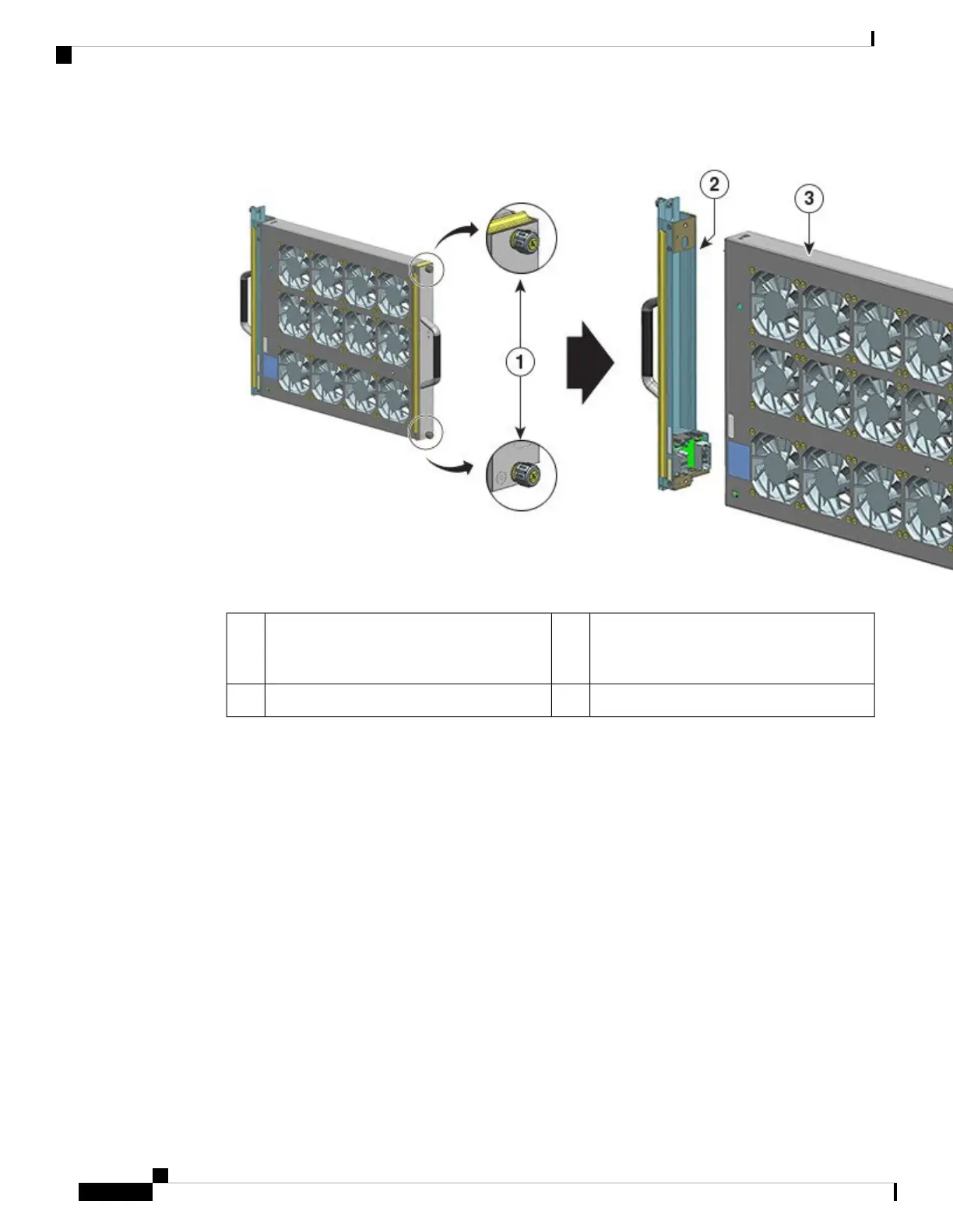
Fan tray ready for installation from the front3Captive installation screws on the front of the
fan tray assembly that have to be loosened
(the side with the fan STATUS LED)
1
--The adapter, detatched from the fan tray2
The adapter module is not used or replaced when installed from the front. It can be scrapped or stored for
future use.
c) Keep the replacement fan tray on an anti-static mat and within arm's reach.
Step 2 Enable the service mode
In a system that is powered on, enabling the service mode for the system-allotted 10 minutes safely assures
fan-less operation for four minutes. See Enabling the Service Mode Before Removing a Fan Tray, on page
86
Proceed with removing and replacing the fan tray immediately after the service mode self-terminates.
Important
Step 3 Remove the fan tray from the chassis - loosen the two captive installation screws on the front panel of the fan
tray (the side with the fan STATUS LED).
Cisco Catalyst 9400 Series Switches Hardware Installation Guide
88
Removing and Replacing FRUs
Removing a Fan Tray from the Front

 Loading...


