Before you continue to install the terminal block ground wires, stop and perform Step 4.
Caution
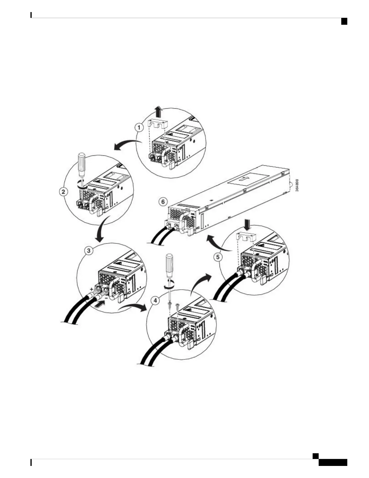
Step 4 Prevent any contact with metal lead on the ground wire and the plastic cover.
Wrap the positive and negative lead cables with sleeving. Insulate the lug with shrink sleeving for each lead wire if using
noninsulated crimp terminals. Sleeving is not required for insulated terminals.
Figure 15: DC Power Supply Terminal Block Ground Cable Lugs
This illustration shows the DC power supply for the s.
Note
Step 5 For easier cable-management, insert the negative lead cable first.
Replace the ground lug with a cable in the following order:
• Wire terminal
Cisco Catalyst CW9800H1 and CW9800H2 Wireless Controllers Hardware Installation Guide
85
Removing and Replacing FRUs
Wiring the DC Input Power Source