The port LEDs behave as follows:
• Off—Indicates the port is not enabled by software.
• Amber—Indicates the port is enabled by software but there is a problem with the link.
• Green—Indicates the port is enabled by software and there is valid link.
Management and Storage Connections
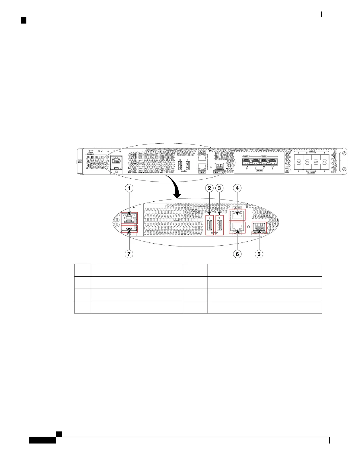
The following figure shows the management and storage connections for the Cisco Catalyst CW9800H1
Wireless Controller and the Cisco Catalyst CW9800H2 Wireless Controller.
Figure 5: Management and Storage Connections for Cisco Catalyst CW9800H1 and CW9800H2 Wireless Controllers
RP—1-GE/10-GE SFP port5RJ-45 compatible console port1
RP—RJ-45 1 GE redundancy port6USB port 02
CON-Mini USB console port7USB port 13
SP—RJ-45 1 GE management port4
LEDs
The following figure shows the LEDs on the front panel of the Cisco Catalyst CW9800H1 Wireless Controller
and Cisco Catalyst CW9800H2 Wireless Controller.
Cisco Catalyst CW9800H1 and CW9800H2 Wireless Controllers Hardware Installation Guide
8
Overview
Management and Storage Connections