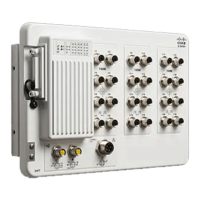
Temperature DeratingWall GapSwitch
No deratingFlushIE9310 GE Fiber
No derating0.75 inIE9320 GE Fiber
5° C deratingFlushIE9320 GE Fiber
For mounting railway-application equipment and for EN50155 standard compliance, the switch must
be installed only in a rack mid-mounting position. If you install the switch in a front rack-mounting
(cable side or power supply side) position or in a wall-mounting position, a mechanical failure can occur
that results in the switch becoming detached from the rack. (Statement 403)
Warning
The following minimum clearances apply when mounting the switch vertically in an enclosure:
• Sides of switch (facing up and facing down): 3.75 in (9.52 cm)
• Port side 3.0 in (7.62 cm)
• Power supply side: 5.25 in (13.33 cm)
• Cover side (not facing wall): 1.75 in (4.44 cm)
• Base side (facing wall): 0 in (0 cm)
Attach Wall-Mount Brackets
Attach the brackets to the switch so that you can attach it to a wall.
Attach the switch to the wall, as shown in the following illustration:
Cisco Catalyst IE9300 Rugged Series Switch Hardware Installation Guide
27
Switch Installation
Attach Wall-Mount Brackets