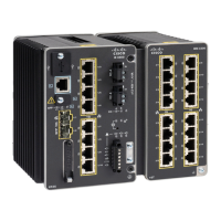
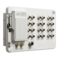
Step 2 Verify that the PSU LED and PSU OK LED is blinking red or is off.
Step 3 Use a Phillips screwdriver to loosen the captive screws that secure the power-supply module to the switch, as shown in
the following illustration.
Hot surface. (Statement 1079)
Warning
Figure 31: Removing the Screws
Step 4 Remove the power-supply module from the power slot, as shown in the following illustration.
The power-supply module might be hot.
Note
Step 5 Install a new power-supply module or a blank cover.
To prevent exposure to hazardous voltages and to contain electromagnetic interference (EMI), either a
power-supply module or a blank cover must be in each power-supply module slot at all times.
Caution
Figure 32: Removing the Power-Supply Module
Cisco Catalyst IE9300 Rugged Series Switch Hardware Installation Guide
47
Power Supply Installation
Remove the Power-Supply Module
 Loading...


