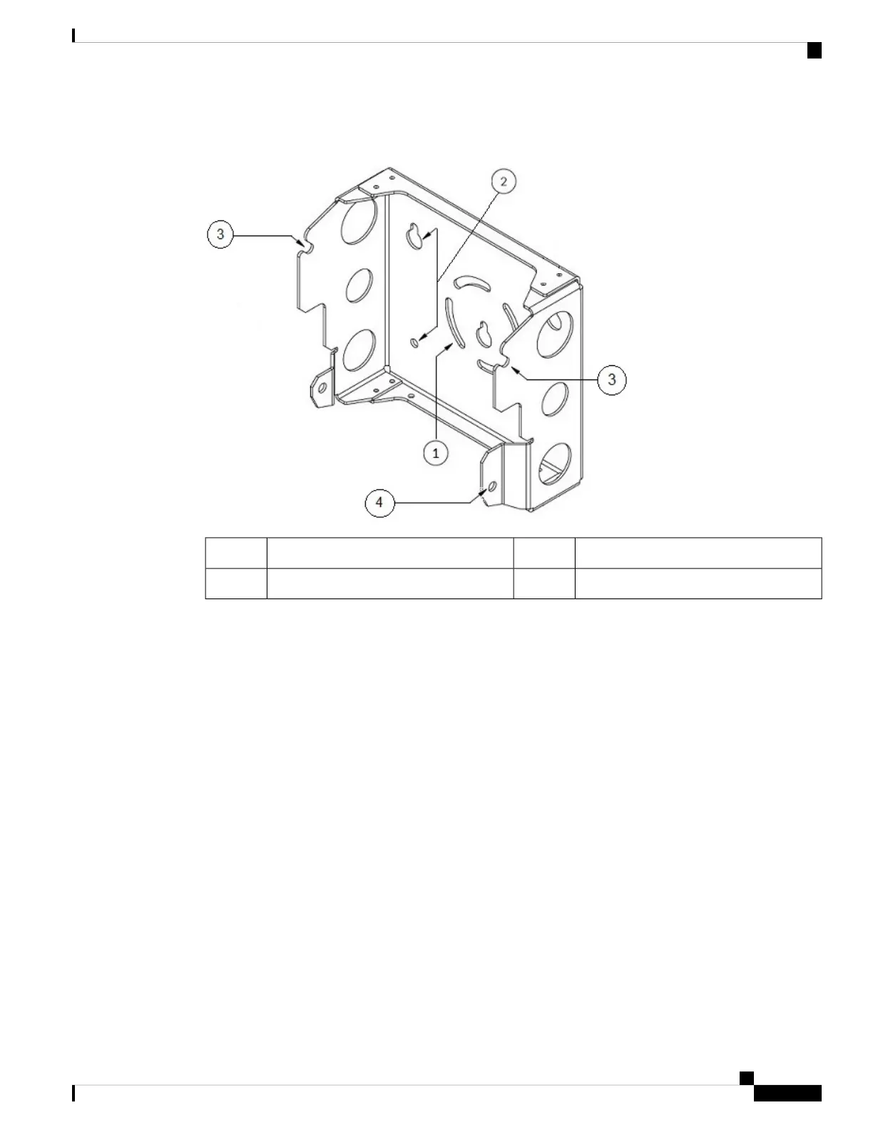
Figure 12: Screw Hole Locations on the Mounting Bracket
Hands-free attach point3Mounting slots1
Second support bolt hole4Mounting holes2
Step 2 Use four customer-supplied screws and optional screw anchors to attach the mounting plate to the mounting
surface.
If necessary, use suitable screw anchors and an exterior-grade plywood backboard to mount the
access point to stucco, cement, or drywall.
Note
Step 3 Screw a M8 x16 bolt in the top support bolt hole on each side the access point. Do not screw the bolt all the
way in; leave approximately a 0.25 inch (0.635 cm) space.
Step 4 Position the two bolts on the access point onto the hands-free attach points on each side of the mounting
bracket. Ensure that the access point cover is facing out. Never leave the access point unattended until fully
installed.
Cisco Catalyst IW6300 Heavy Duty Series Access Point Hardware Installation Guide
25
Installing the Access Point
Mounting the Access Point on a Wall

 Loading...