8 LAN 3
9
LAN 4
10 VGA video port (DB-15)
Table 3 Rear Panel Ports (continued)
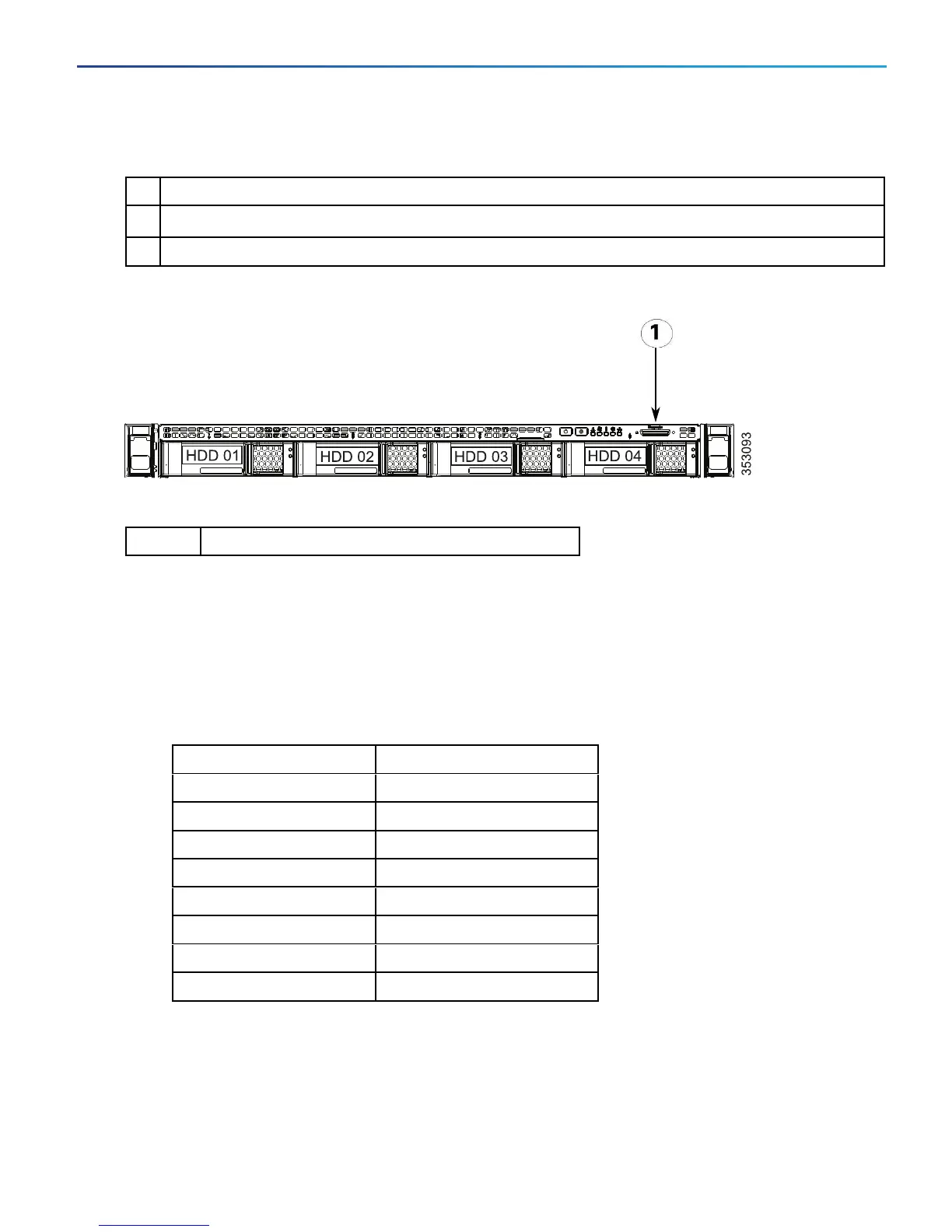
Figure 2 Front Panel Showing KVM Connector
1 KVMconnector
Table 4 Front Panel Ports
Connect Using the Serial Port
1. Connect the Ethernet LAN cable from the LAN 1 port on the rear of the unit to your network.
The LAN 1 port is the left-hand port of the dual port adapter on the rear panel of the unit (shown in Figure 1
Rear Panel Showing Ports, page 10).
2. Connect a serial cable from the serial port on the rear of the unit to the serial port on a PC (see Figure 1 Rear
Panel Showing Ports, page 10).
The serial cable used must be a cross-over cable. The pin assignment for the serial cable is:
Male RJ45 pin Female DB9 pin
1 8
2 6
3 TXD 2
4 GND 5
5 GND 5
6 RXD 3
7 4
8 7
Note:If there is no DB9 port on your PC, a DB9 to USBserial port adapter is required.
11
Cisco Expressway CE1100 Appliance Installation Guide
Configure
 Loading...