Step 4
Attach a cable management bracket to each slide rail locking bracket using the four 8-32 x .375" countersink Phillips
head screws provided in the accessory kit.
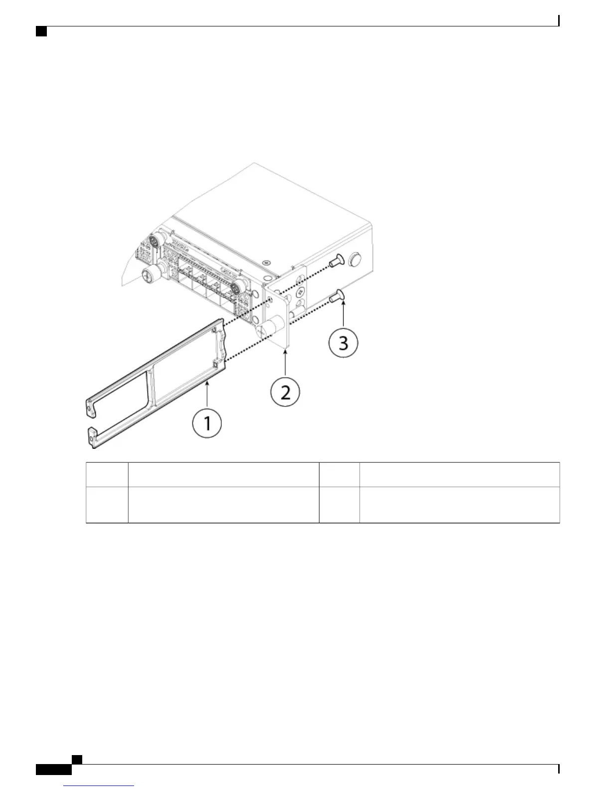
Figure 37: Attach the Cable Management Bracket to the Slide Rail Locking Bracket
Slide rail locking bracket2Cable management bracket1
8-32 x .375" countersink Phillips head screws
(2 per side)
3
Step 5
Connect the cables to the ports. See Connect Cables, Turn on Power, and Verify Connectivity, on page 55 for the
procedure.
If you are installing the FIPS opacity shield after the initial product installtion, the cables will already be connected. If
the attached cables do not have enough slack to route them through the cable mounting brackets (as shown below), you
will have to turn the power off on the Firepower 4100, remove the cables, route the cables through the cable mounting
brackets, reattach the cables, and continue with step 7 below.
Make sure that the cables have enough slack to route them through the cable mounting brackets (as shown in
step 6 below).
Note
If you are installing the FIPS opacity shield after the initial product installation, the cables are already
connected. If the attached cables do not have enough slack to route them through the cable mounting brackets
(as shown below), power down the appliance, remove the cables, route the cables through the cable mounting
brackets, reattach the cables, and continue with step 7 below.
Important
Cisco Firepower 4100 Series Hardware Installation Guide
52
Mount and Connect
Install the FIPS Opacity Shield
 Loading...


