16
Alarm Connector
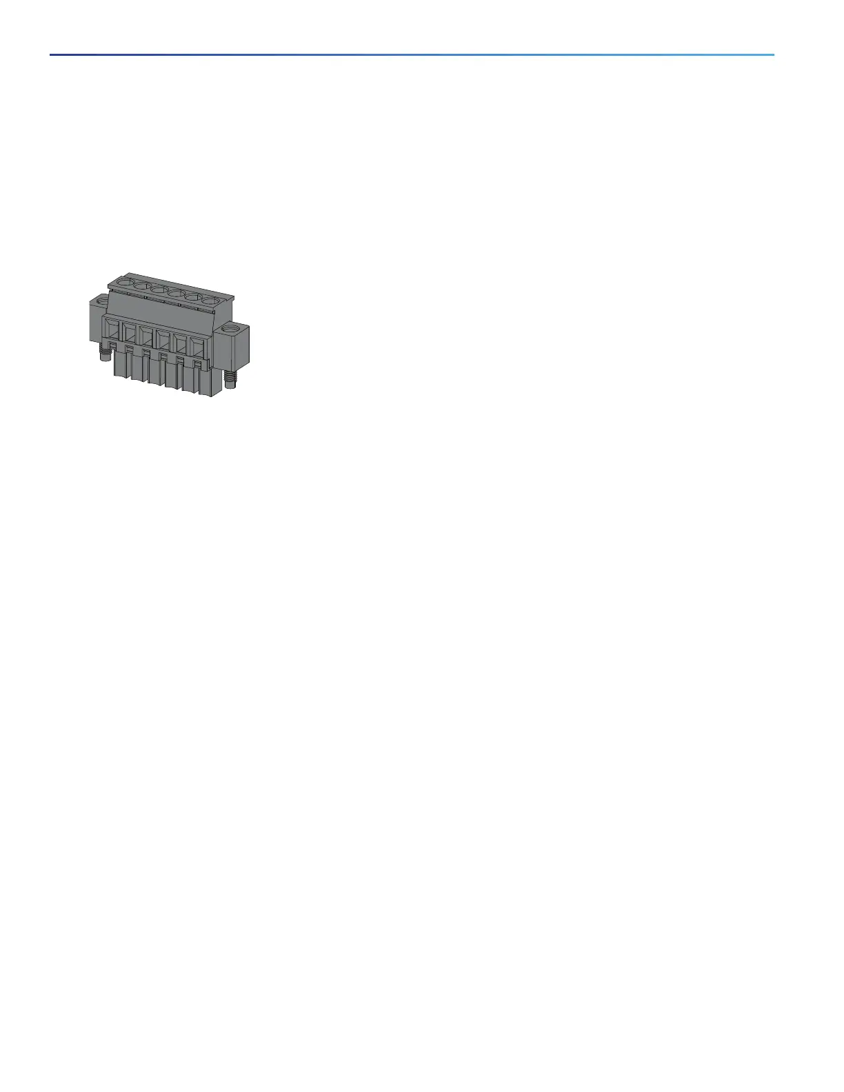
You connect the alarm signals to the switch through the alarm connector. The switch supports two alarm inputs and one
alarm output relay. The alarm connector is on the bottom right of the front panel. See Figure 3 on page 11.
The alarm connector provides six alarm wire connections. The connector is attached to the switch front panel with the
provided captive screws.
Figure 7 Alarm Connector
Both alarm input circuits can sense if the alarm input is open or closed. The alarm inputs can be activated for
environmental, power supply, and port status alarm conditions. From the CLI, you can configure each alarm input as an
open or closed contact.
The alarm output circuit is a relay with a normally open and a normally closed contact. The switch is configured to detect
faults that are used to energize the relay coil and change the state on both of the relay contacts: normally open contacts
close, and normally closed contacts open. The alarm output relay can be used to control an external alarm device, such
as a bell or a light.
See the switch software configuration guide for instructions on configuring the alarm relays.
For more information about the alarm connector, see Cable and Connectors, page 85.