92
Figure 54 Four Twisted-Pair Straight-Through Cable Schematic for 1000BASE-T Ports
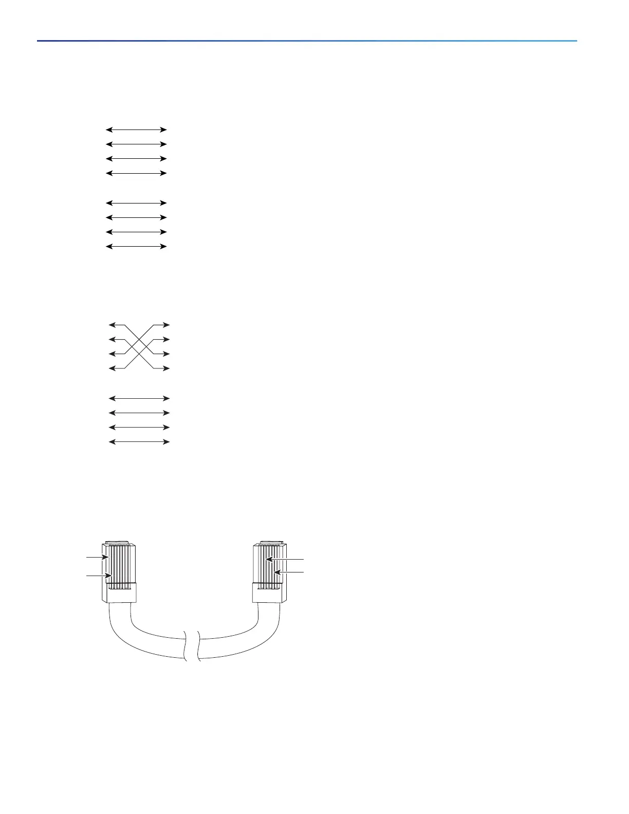
Figure 55 Four Twisted-Pair Crossover Cable Schematics for 1000BASE-T Ports
To identify a crossover cable, hold the cable ends side-by-side, with the tab at the back. The wire connected to pin 1
on the left end should be the same color as the wire connected to pin 3 on the right end. The wire connected to pin 2
on the left end should be the same color as the wire connected to pin 6 on the right end.
Figure 56 Identifying a Crossover Cable
Console Port Adapter Pinouts
The console port uses an 8-pin RJ-45 connector, which is described in b and Table 23 on page 93. If you did not order
a console cable, you need to provide an RJ-45-to-DB-9 adapter cable to connect the switch console port to a PC
console port. You need to provide an RJ-45-to-DB-25 female DTE adapter if you want to connect the switch console
1 TP0+
2 TP0-
3 TP1+
6 TP1-
1 TP0+
2 TP0-
3 TP1+
6 TP1-
Switch Router or PC
4 TP2+
5 TP2-
7TP3+
8 TP3-
4 TP2+
5 TP2-
7TP3+
8 TP3-
65271
1 TP0+
2 TP0-
3 TP1+
6 TP1-
1 TP0+
Switch Switch
2 TP0-
3 TP1+
6 TP1-
4 TP2+
5 TP2-
7 TP3+
8 TP3-
4 TP2+
5 TP2-
7 TP3+
8 TP3-
65274
Pin 1
Pin 2
273807
Pin 6
Pin 3