87
Console Port
The switch has two console ports: a USB 5-pin mini-Type B port on the front panel (see Figure 50 on page 87) and an
RJ-45 console port on the rear panel.
Figure 50 USB Mini-Type B Port
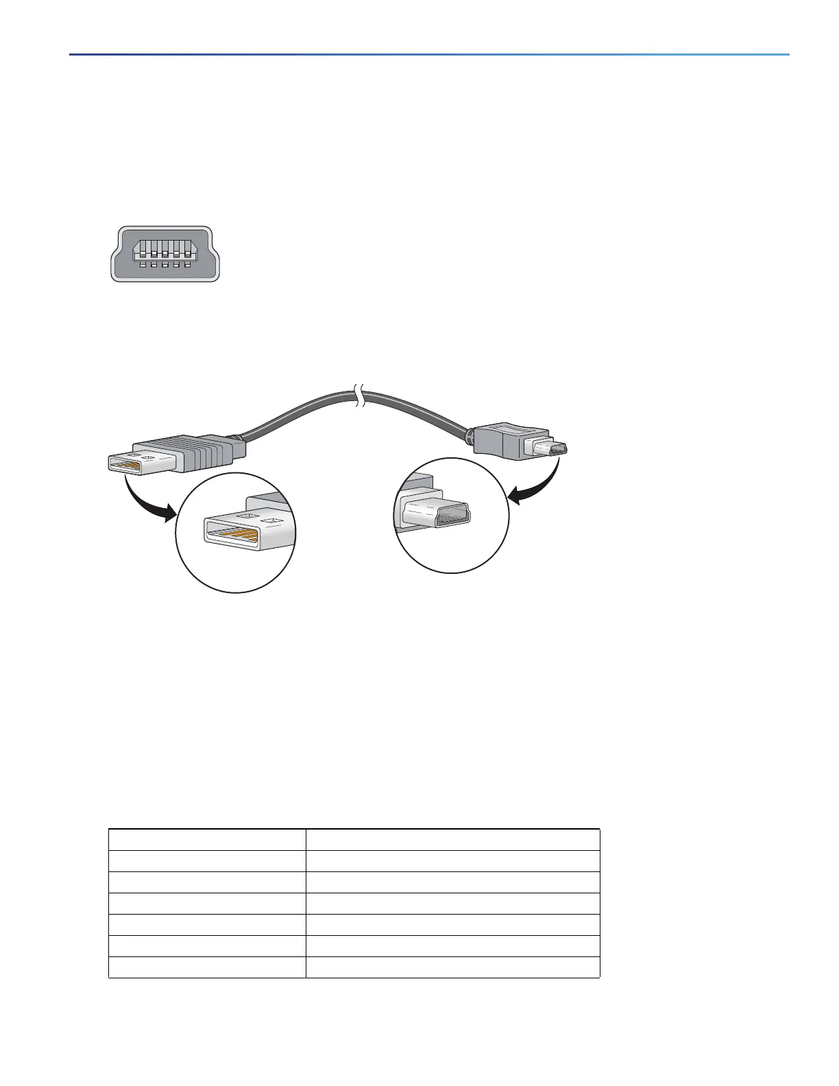
The USB console port uses a USB Type A to 5-pin mini-Type B cable, shown in Figure 51 on page 87. The USB Type
A-to-USB mini-Type B cable is not supplied. You can order an accessory kit (part number 800-33434) that contains this
cable.
Figure 51 USB Type A-to-USB 5-Pin Mini-Type B Cable
The RJ-45 console port uses an 8-pin RJ-45 connector (see Table 22 on page 93 and Table 23 on page 93). The
supplied RJ-45-to-DB-9 adapter cable is used to connect the console port of the switch to a console PC. You need to
provide an RJ-45-to-DB-25 female DTE adapter if you want to connect the switch console port to a terminal. You can
order a kit (part number ACS-DSBUASYN=) containing that adapter. For console port and adapter pinout information,
see Table 22 on page 93 and Table 23 on page 93.
Alarm Port
For information on alarm ratings, see the Alarm Ratings, page 83.
The labels for the alarm connector pin-outs are on the switch panel and are displayed in Table 18 on page 87.
253405
Table 18 Alarm Connector Labels (Top to Bottom)
Label Connection
NO Alarm Output Normally Open (NO) connection
COM Alarm Output Common connection
NC Alarm Output Normally Closed (NC) connection
IN2 Alarm Input 2
REF Alarm Input Reference Ground connection
IN1 Alarm Input 1