56
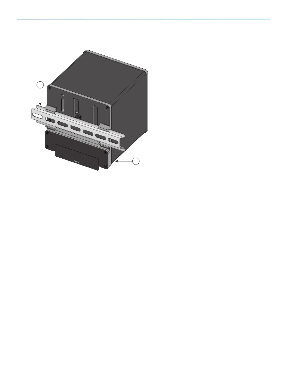
Figure 31 Position the Hooks Over the DIN Rail
3. Push the switch toward the DIN rail to cause the spring-loaded latch at the bottom rear of the switch to move down,
and snap into place.
After the switch is mounted on the DIN rail, connect the power and alarm wires, as described in the Connecting Alarm
Circuits, page 57.
For configuration instructions about the CLI setup program, see the Configuring the Switch with the CLI-Based Setup
Program, page 95
For instructions on how to remove the switch from a DIN rail, see the Removing the Switch from a DIN Rail, page 56.
Removing the Switch from a DIN Rail
To remove the switch from a DIN rail, follow these steps:
1. Ensure that power is removed from the switch, and disconnect all cables and connectors from the front panel of the
switch.
2. Insert a tool such as a flathead screwdriver in the slot at the bottom of the spring-loaded latch and use it to release
the latch from the DIN rail. See Figure 32 on page 57.
3. Pull the bottom of the switch away from the DIN rail, and lift the hooks off the top of the DIN rail. See Figure 32.
1 DIN Rail 2 Switch