48
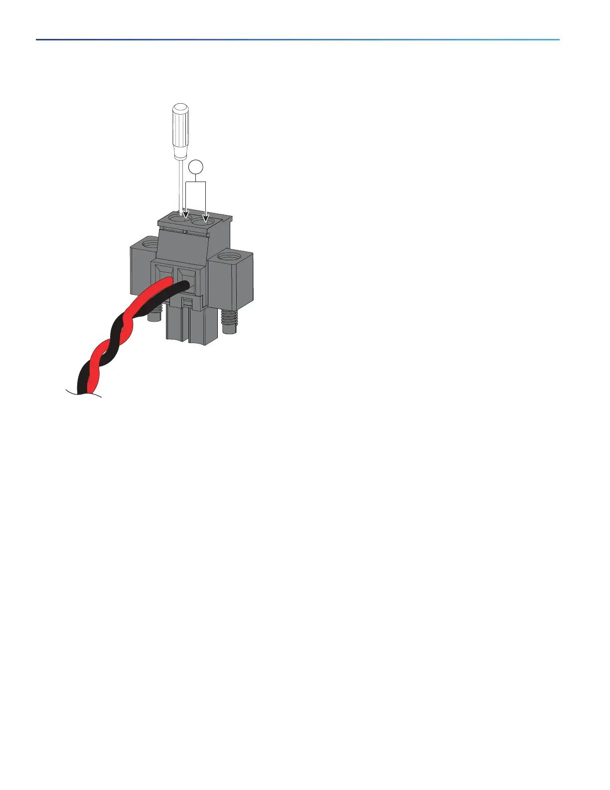
Figure 26 Torquing the Power Connector Captive Screws
8. Connect the other end of the positive wire to the positive terminal on the DC power source, and connect the other
end of the return wire to the return terminal on the DC power source.
When you are testing the switch, one power connection is sufficient. If you are installing the switch and are using a
second power source, repeat steps 4 through 8 using the second power connector.
Figure 27 on page 49 shows the completed DC-input wiring on a power connector for a primary power source and
an optional secondary power source.
1 Power connector captive screws