69
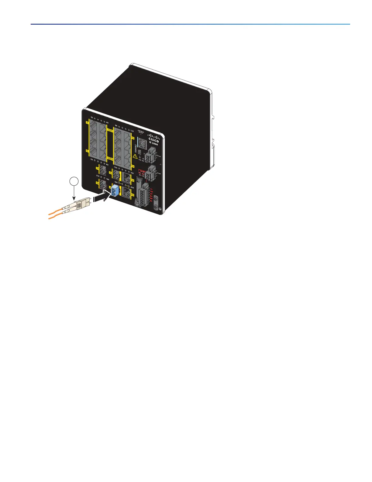
Figure 43 Connecting to a Fiber-Optic SFP Module Port
3. Insert the other cable end into a fiber-optic receptacle on a target device.
4. Observe the port status LED:
— The LED turns green when the switch and the target device have an established link.
— The LED turns amber while the STP discovers the network topology and searches for loops. This process takes
about 30 seconds, and then the port LED turns green.
— If the LED is off, the target device might not be turned on, there might be a cable problem, or there might be a
problem with the adapter installed in the target device. See Troubleshooting, page 73 for solutions to cabling
problems.
5. If necessary, reconfigure and restart the switch or the target device.
Connecting to a 1000BASE-T SFP Module
Follow these steps to connect a CAT5 cable to a 1000BASE-T SFP module:
1. When connecting to servers, workstations, and routers, insert a four twisted-pair, straight-through cable in the
RJ-45 connector. When connecting to switches or repeaters, insert a four twisted-pair, crossover cable.
When connecting to a 1000BASE-T device, use a four twisted-pair CAT5 cable.
2. Insert the other cable end in an RJ-45 connector on a target device.
3. Observe the port status LED.
— The LED turns green when the switch and the target device have an established link.
1 LC connector
16TC
±12/24/48
0.5-3.0A
331561
1