B-13
Cisco IE 3000 Switch Hardware Installation Guide
Appendix B Installation In a Hazardous Environment
Adding Modules to the Switch
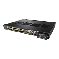
Step 3 Push up the upper module latches (at the top of the switch and the expansion module). See Figure B-4.
Push down the lower module latches (at the bottom of the switch and the expansion module).
Figure B-4 Pushing the Module Latches Up
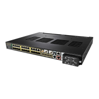
Step 4 Align the connectors on the switch and the module, and slide the switch and the expansion module
together to make the connection. See Figure B-5.
Figure B-5 Connecting the Switch and the Module
Step 5
Push the upper module latches down and the lower latches up. See Figure B-6.
201824
 Loading...

