B-23
Cisco IE 3000 Switch Hardware Installation Guide
Appendix B Installation In a Hazardous Environment
Verifying Switch Operation
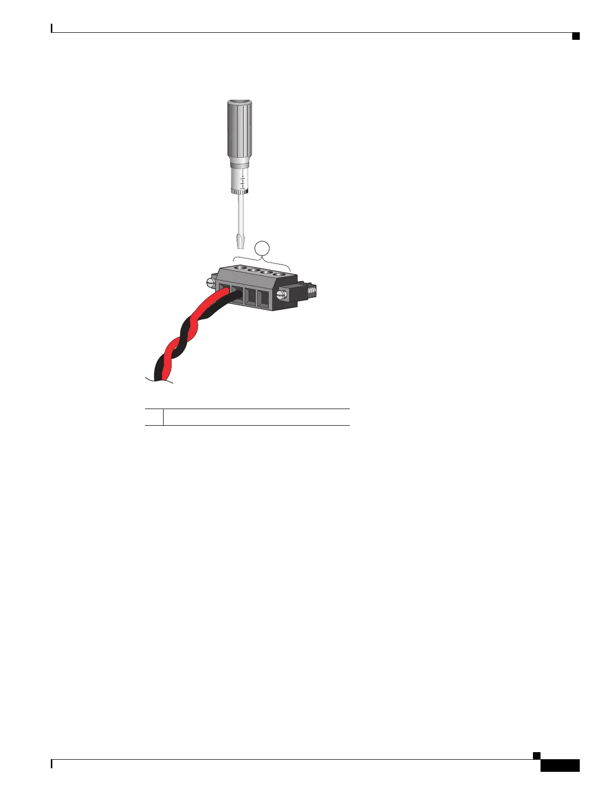
Figure B-15 Torquing the Power and Relay Connector Captive Screws
Step 7
Connect the other end of the positive wire (the one connected to V) to the positive terminal on the DC
power source, and connect the other end of the return wire (the one connected to RT) to the return
terminal on the DC power source.
When you are testing the switch, one power connection is sufficient. If you are installing the switch and
are using a second power source, repeat Step 4 through Step 7 using a second power and relay connector.
1 Power and relay connector captive screws
 Loading...


