2-17
Cisco IE 3000 Switch Hardware Installation Guide
Chapter 2 Switch Installation
Verifying Switch Operation
Figure 2-10 Crimping the Ring Terminal
Step 4
Slide the ground screw through the ring terminal.
Step 5 Insert the ground screw into the functional ground screw opening on the front panel.
Step 6 Use a ratcheting torque screwdriver to tighten the ground screw and ring terminal lug to the switch front
panel to 8.5 in-lb. The torque should not exceed 8.5 in-lb (0.9 Nm). See Figure 2-11.
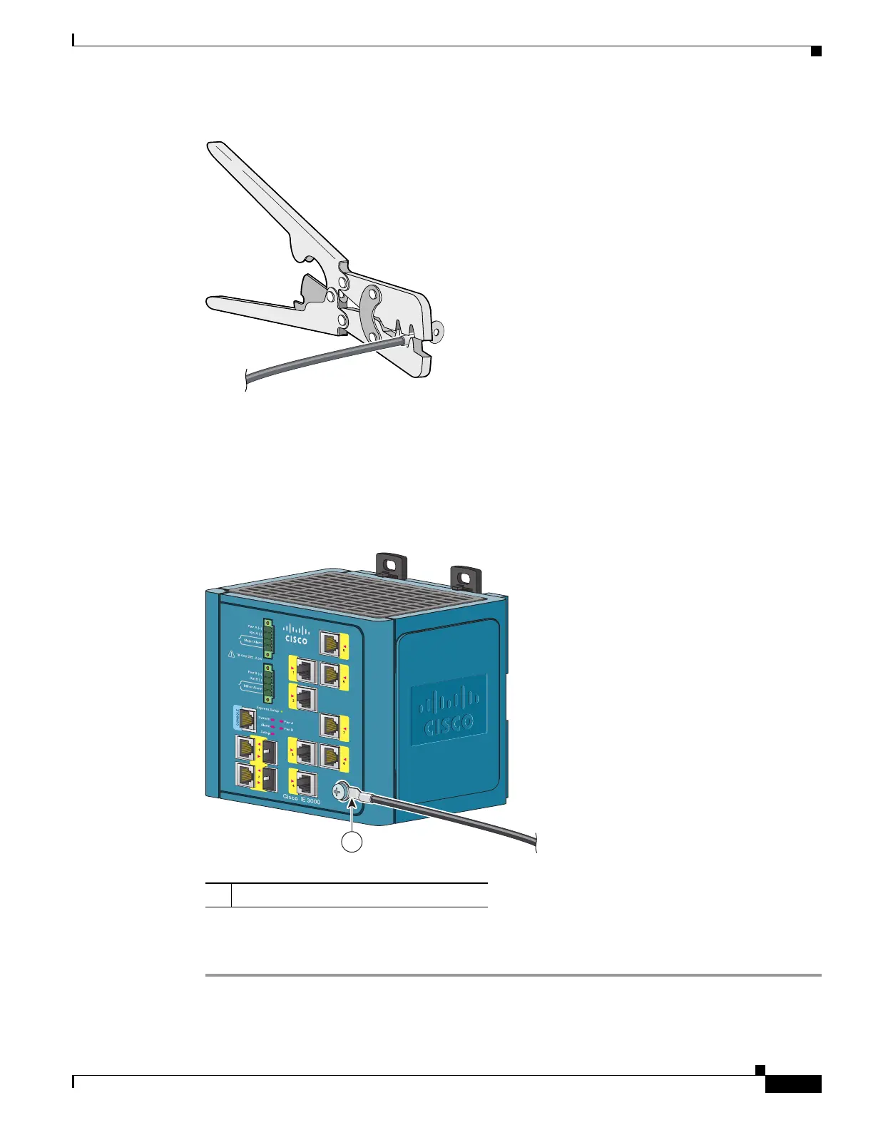
Figure 2-11 Attaching the Ground-Lug Screw
Step 7
Attach the other end of the ground wire to a grounded bare metal surface, such as a ground bus, a
grounded DIN rail, or a grounded bare rack.
1 Ground cable with ring terminal lug
1
201696

 Loading...


