Installing 100/1000BASE-T SFP Modules
Table 11: 100/1000BASE-T SFP Modules
Uplink SupportDownlink SupportModel Number
10/100/100010/100/1000GLC-T
10/100/100010/100/1000GLC-TE
The 100/1000BASE-T (copper) SFP transceiver, seen in the following figure, has a bale-clasp locking
mechanism that secures the transceiver in the module socket. The SFP network interface is an RJ-45 connector.
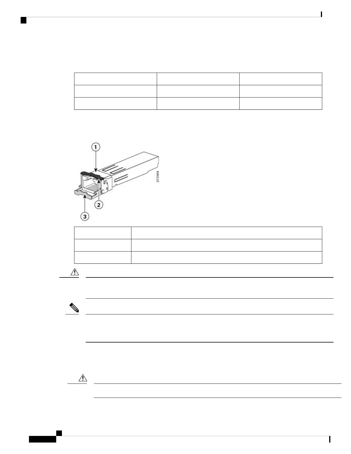
Figure 17: 1000BASE-T SFP Transceiver
RJ-45 connector1
Bale-clasp latching mechanism in the closed (locked) position.2
Bale-clasp latching mechanism in the open (unlocked) position.3
To comply with GR-1089 intrabuilding lightning immunity requirements, you must use grounded, shielded,
twisted-pair, CAT5 cabling.
Caution
When connecting to a 100/1000BASE-T-compatible server, workstation, or router, use four twisted-pair,
straight-through CAT5 cabling for the SFP transceiver port. When connecting to a 100/1000BASE-T-compatible
switch or repeater, use four twisted-pair, crossover CAT5 cabling.
Note
To install a 100/1000BASE-T SFP transceiver:
1. Attach an ESD-preventive wrist strap to your wrist and to the ESD ground connector on the chassis or to
a properly grounded bare metal surface.
To avoid ESD damage, handle the SFP by its sides; do not touch the connector pins.
Caution
Cisco IE 4010 Switch Hardware Installation Guide
30
Switch Installation
Installing 100/1000BASE-T SFP Modules