Power-Supply Module LEDs
The switch power-supply module LEDs are labeled PSU1 and PSU2 (on the switch) and PSU OK (on the
power-supply module). They show whether power-supply modules 1 and 2 are receiving power.
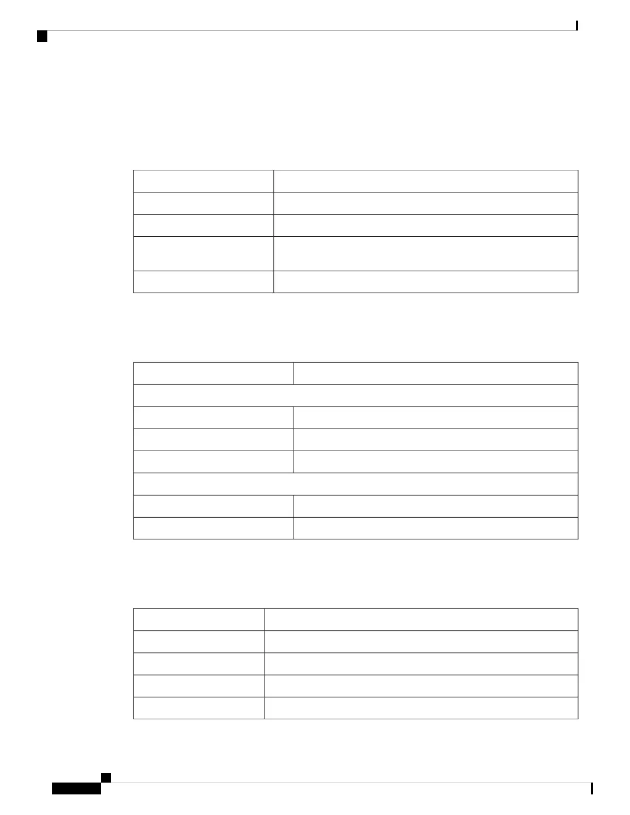
Table 5: Power Supply Module LEDs
System StatusColor
Power-supply module (1 or 2) is not installed.Off
Valid input is present, and the output is within the operating range.Green
Valid input is present, and the output is outside the operating range or is
not present.
Red
Power-supply module (1 or 2) is installed but valid input is not present.Blinking red
Alarm LEDs
Table 6: Alarm LEDs
System StatusColor
1-4 Input Alarms
Alarm not present
Green
Minor alarm presentRed
Major alarm presentBlinking red
Output Alarm
Alarm not present
Green
Alarm condition presentRed
SD Flash Memory Card LED
Table 7: SD Flash Card LED
System StatusColor
Unsupported SD flash memory card is detected.Fast blinking amber
SD flash memory card is not present.Slow blinking amber
SD flash memory card is functioning.Green
SD flash memory card transfer in progress.Blinking green
Cisco IE 4010 Switch Hardware Installation Guide
10
Product Overview
Power-Supply Module LEDs