Figure 36: Fiber-Optic SFP Module LC Connector
Invisible laser radiation may be emitted from disconnected fibers or connectors. Do not stare into beams or
view directly with optical instruments. Statement 1051
Warning
Console Port
The switch has two console ports: a USB 5-pin mini-Type B port (see the following figure) and an RJ-45
(RS-232) console port.
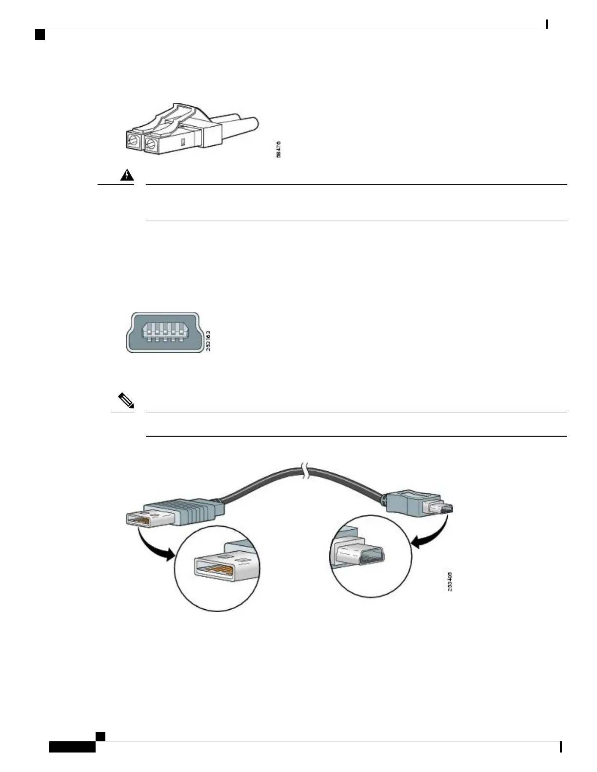
Figure 37: USB Mini-Type B Port
The USB console port uses a USB Type A to 5-pin mini-Type B cable. The USB Type A-to-USB mini-Type
B cable is not supplied. You can order an accessory kit that contains this cable.
When running Linux, access the USB Console using Minicom instead of Screen.
Note
Figure 38: USB Type A-to-USB 5-Pin Mini-Type B Cable
The RJ-45 console port uses an 8-pin RJ-45 connector. An RJ-45-to-DB-9 adapter cable is used to connect
the console port of the switch to a console PC. You need to provide a RJ-45-to-DB-25 female DTE adapter
if you want to connect the switch console port to a terminal. You can order a kit (part number
ACS-DSBUASYN=) containing that adapter. For console port and adapter pinout information, see Console
Ports, on page 5.
Cisco IE 4010 Switch Hardware Installation Guide
62
Cable and Connectors
Console Port