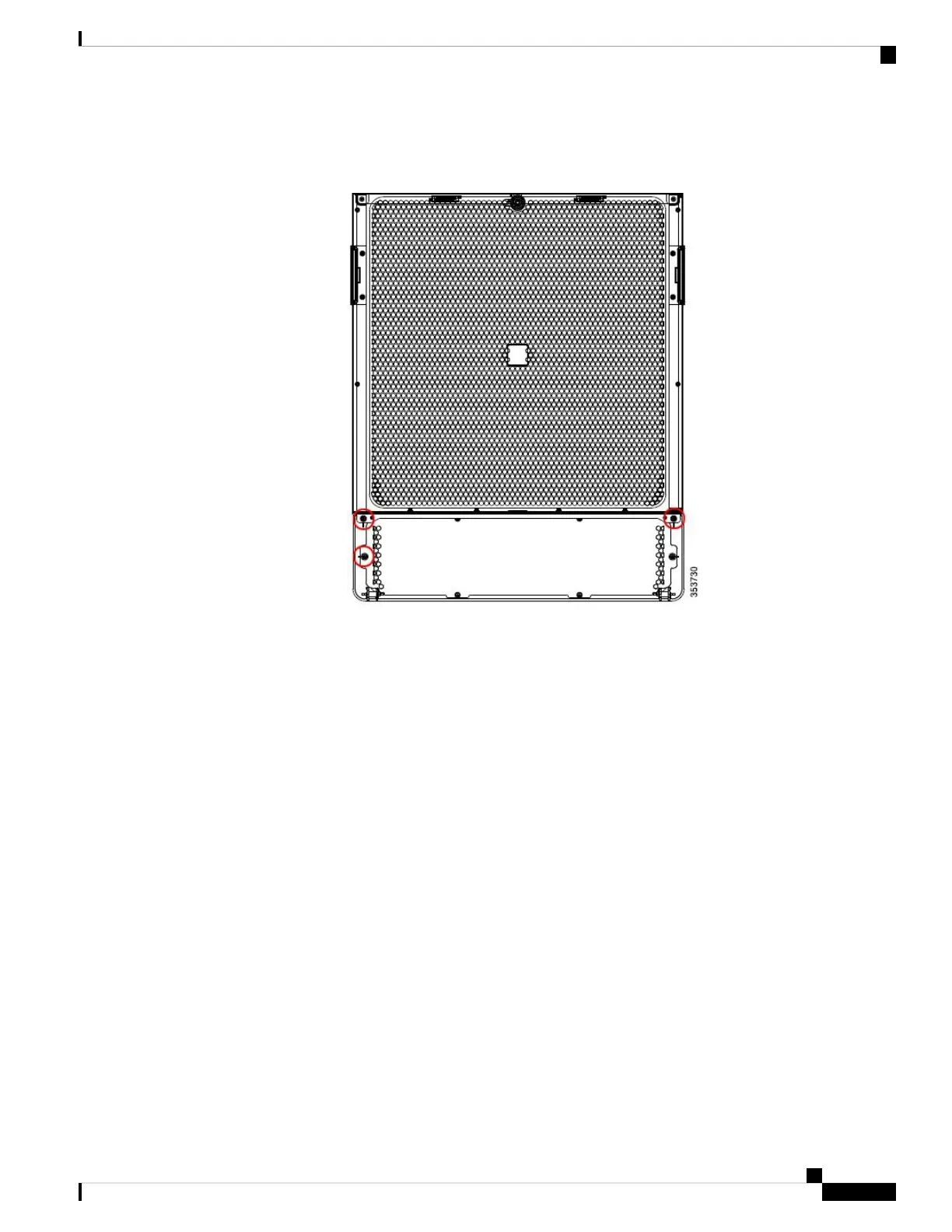
The following figure shows the 3 screws (circled) that have to be removed.
Figure 11: Front ID Door
Step 2 Add the grounding cable to the left side of the front ID door to connect the top and bottom metal plates.
Step 3 Tighten the screw to 7 in-lb (0.79 N-m) of torque to provide proper bonding.
Step 4 Install another grounding cable to the right side of the front ID door.
The following figure shows the location of the 2 grounding cables.
Cisco Nexus 7710 Switch Site Preparation and Hardware Installation Guide
31OL-30452-01.
Installing the Chassis
Grounding the Front ID Door

 Loading...


