Full redundancy mode
This mode provides both power-supply (n+1) and input-source (grid) redundancies. As happens with the
input-source redundancy mode, this mode allocates half of the power supplies to provide available power
and the other half of the power supplies to provide the reserve power. One of the reserve power supplies
can alternatively be used to provide power if a power supply supplying the available power fails.
Guidelines for Configuring Power Redundancy Modes
The amounts of available and reserve power depend on the power redundancy mode that you specify and the
number of power supplies installed in the switch. For each redundancy mode, consider the following:
Combined mode
The available power equals the combined output of all installed power supplies. There is no reserve
power. You activate this mode by using the power redundancy-mode combined command.
For example, if the power requirement for a switch is 5.2 kW and the switch has one 3-kW power supply
with 220 V input and 3.0-kW output, consider the following power planning scenarios:
• Scenario 1—no added power supplies
If you do not add a power supply unit, the available power (3.0 kW) is insufficient for the switch
power requirement of 5.2 kW, so the switch powers the supervisor modules, fabric modules, and
fan trays, before powering as many I/O modules as the remaining available power can support (one
or more I/O modules will not be powered).
• Scenario 2—install an extra 3-kW power supply
If you install an additional 3-kW power supply unit that can output 3.0 kW, the available power
becomes 6.0 kW. The increased amount of available power exceeds the switch power requirement
of 5.2 kW, so all of the modules and fan trays in the switch can power up.
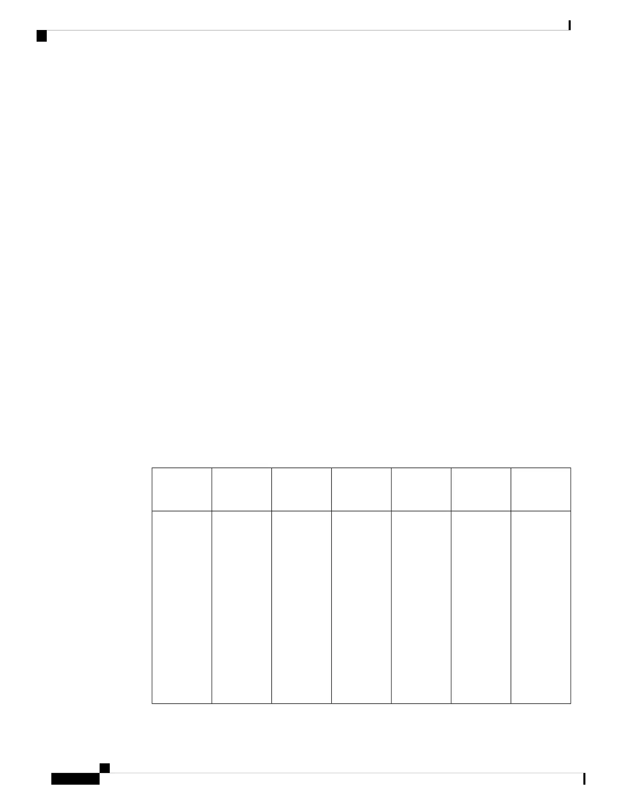
The following table shows the results for each scenario.
ResultReserve
Power
Available
Power
Power
Supply 2
Output
Power
Supply 1
Output
Power
Requirement
Scenario
Available
power is less
than the
power
requirement
for the
switch, so
you cannot
power the
entire switch
(some of the
I/O modules
will not be
able to power
up).
—3.0 kW—3.0 kW5.2 kW1
Cisco Nexus 7710 Switch Site Preparation and Hardware Installation Guide
OL-30452-01.72
Managing the Switch
Guidelines for Configuring Power Redundancy Modes

 Loading...


