3-53
Cisco UCS C240 Server Installation and Service Guide
OL-25761-01z
Chapter 3 Maintaining the Server
Installing or Replacing Server Components
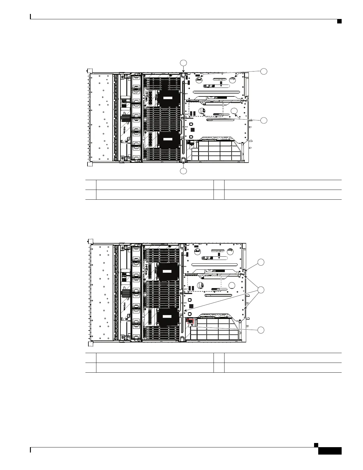
Figure 3-27 Removing the Chassis Mid-Brace and PCIe Risers
Step 3
Connect the 8-to-8 pin power cable adapter to the motherboard connector GPU PWR (see Figure 3-28).
Figure 3-28 GPU PWR Motherboard Connector and PCIe Riser Alignment Slots
Step 4
Connect a GPU power cable to the free end of the 8-to-8 pin adapter (see Figure 3-29):
• If you are installing only one GPU, use the straight GPU power cable.
• If you are installing two GPU cards, use the “Y” GPU power cable.
1 Chassis mid-brace finger-latch 3 PCIe riser 2 finger holes
2 PCIe riser 1 finger holes
SAS2
SAS1
FAN1
FAN2
FAN3
FAN4
FAN5
FAN6
CPU1
CPU2
SAS1
SAS2
Riser 1
Riser 2
SAS1
SAS2
336561
3
2
1
1
1 PCIe riser 1 alignment slot location 3 Motherboard connector GPU PWR
2 PCIe riser 2 alignment slot locations (three)
SAS2
SAS1
FAN1
FAN2
FAN3
FAN4
FAN5
FAN6
CPU1
CPU2
SAS1
SAS2
Riser 1
Riser 2
SAS1
SAS2
1
2
331842
3