3-54
Cisco UCS C240 Server Installation and Service Guide
OL-25761-01
Chapter 3 Maintaining the Server
Installing or Replacing Server Components
Note Do not connect the power cable to the GPU card at this point.
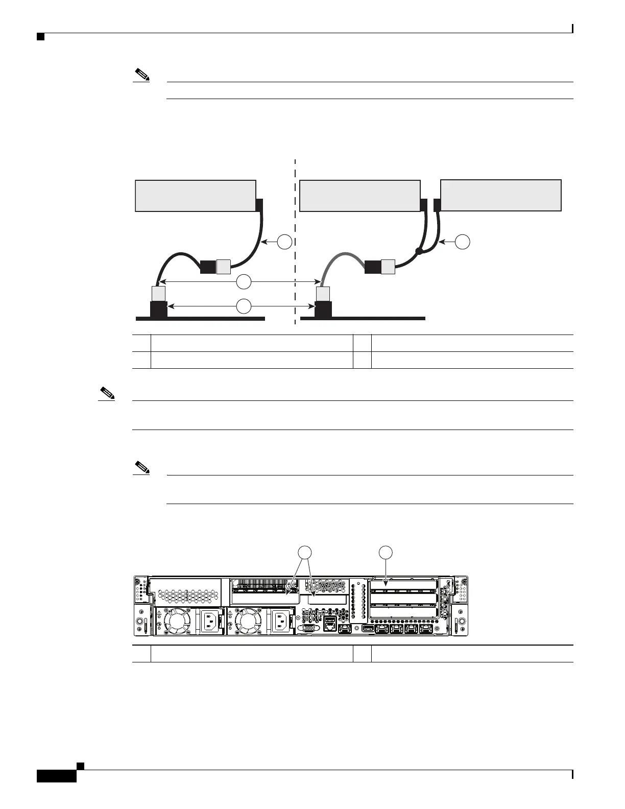
Figure 3-29 Cabling Diagram, Single- and Dual-GPU Card Examples
Note See Configuration Rules, page 3-48 before you install the GPU cards to the risers. Slot population
restrictions apply.
Step 5 Install your first GPU card into PCIe slot 5. See Figure 3-30 for the riser and slot locations.
Note The option ROM for the slot in which you are installing the GPU card must be enabled in the
BIOS Setup Utility or it will not be recognized by the system.
Figure 3-30 Rear Panel, Showing PCIe Risers and PCIe Slots
a. Open the riser’s hinged card retainer and the long-card retainer (see Figure 3-31).
b. Align the GPU card with the socket on the riser, then gently push the card’s edge connector into the
socket. Press evenly on both corners of the card to avoid damaging the connector.
c. Close the hinged card retainer, then the long-card retainer over the end of the card.
1 Motherboard connector GPU PWR 3 Straight GPU power cable for single GPU
2 8-to-8 pin cable adapter 4 Y GPU power cable for dual GPUs
1 PCIe riser 1 slots (Slots 1, 2, 3) 2 PCIe riser 2 slots (Slots 4, 5)
PSU1 PSU2
PCIe 1
PCIe 2
PCIe 3
PCIe 4
PCIe 5
1
2
331841