3-55
Cisco UCS C240 Server Installation and Service Guide
OL-25761-01z
Chapter 3 Maintaining the Server
Installing or Replacing Server Components
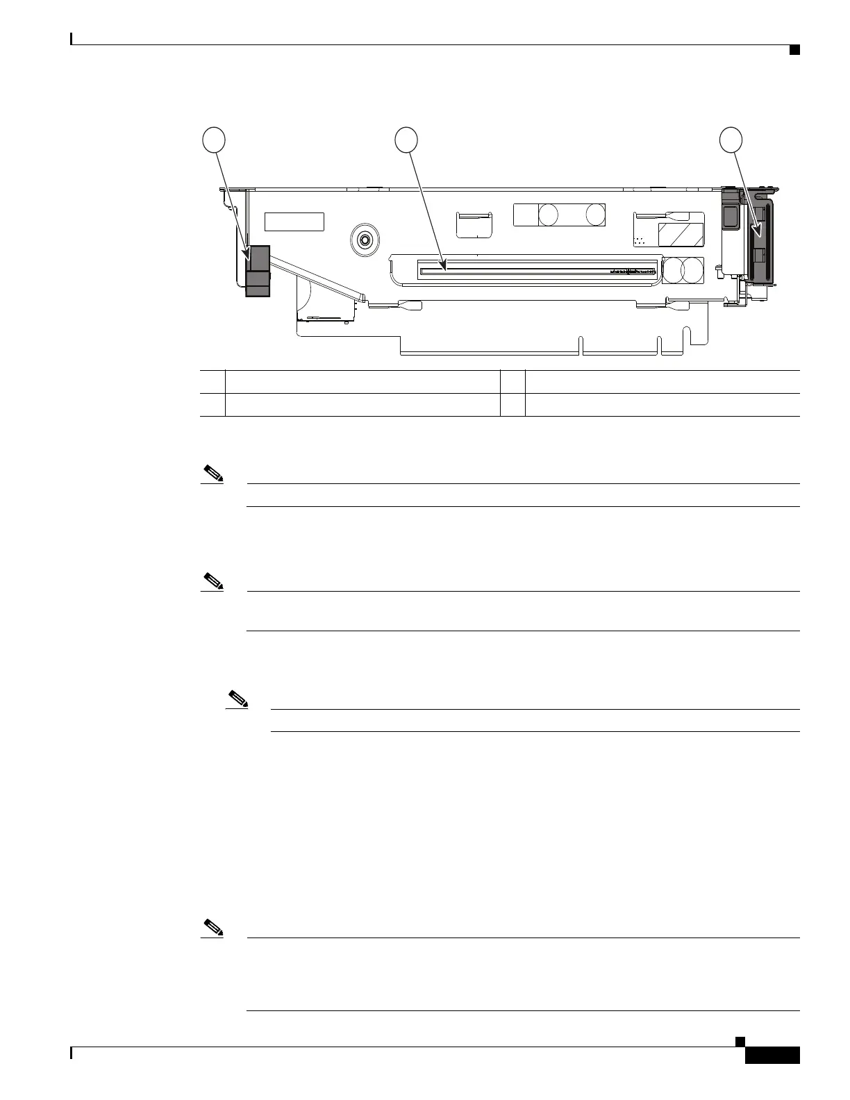
Figure 3-31 PCIe Riser (Slot 5 on PCIe Riser 2 Shown)
Step 6 If you are installing a second GPU card, repeat the actions in Step 5 for PCIe slot 2 on the second riser.
Note When a GPU card is in slot 2, slot 1 is blocked and unavailable for use.
Step 7 Install the new PCIe risers:
a. Install any other PCIe cards that you want to install into the new risers.
Note If you are installing a Cisco UCS Virtual Interface Card (VIC), see the slot restrictions in Special
Considerations for Cisco UCS Virtual Interface Cards, page 3-43.
b. Install riser 2 first. Position the PCIe riser over its socket on the motherboard and over its alignment
slots in the chassis (see Figure 3-28).
Note It is easier to view and position the riser 2 connector over its socket with riser 1 removed.
c. Carefully push down on both ends of the PCIe riser to fully engage its circuit board connector with
the socket on the motherboard. The riser top surfaces should sit flat on the chassis and the mid-brace.
d. Install riser 1.
Step 8 Connect the power cable to the GPU cards. See Figure 3-29.
• If you installed one GPU card, connect the free end of the straight cable to the GPU card power
connector that is underneath the chassis mid-brace.
• If you installed two GPU cards, connect the shorter branch of the Y cable to the GPU card in slot 5.
Connect the longer branch to the GPU card in slot 2.
Note The power connector on the NVIDIA GRID K1 GPU card has only 6 pins, but the power cable
has an 8-pin connector. Plug the 8-pin cable connector into the 6-pin connector on the card,
aligning the clip and keying features for the correct fit. Pins 4 and 8 on the cable connector do
not engage with the connector on the card.
1 Long-card retainer 3 Hinged card retainer for PCIe slot 5
2 Card socket