3-57
Cisco UCS C240 Server Installation and Service Guide
OL-25761-01z
Chapter 3 Maintaining the Server
Installing or Replacing Server Components
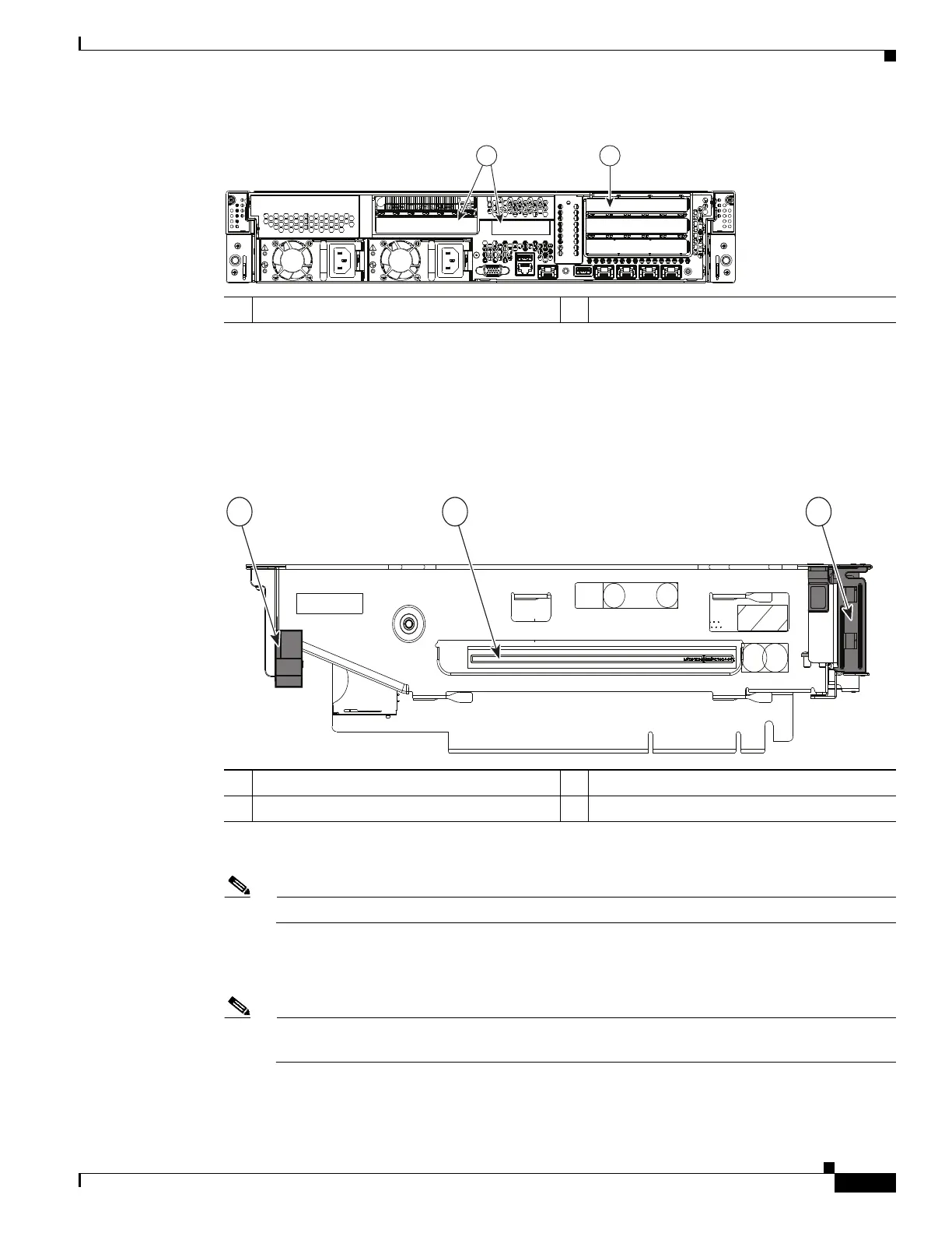
Figure 3-32 Rear Panel, Showing PCIe Risers and PCIe Slots
a. Open the riser’s hinged card retainer and the long-card retainer (see Figure 3-33).
b. Align the GPU card with the socket on the riser, then gently push the card’s edge connector into the
socket. Press evenly on both corners of the card to avoid damaging the connector.
c. Close the hinged card retainer, then the long-card retainer over the end of the card.
Figure 3-33 PCIe Riser (Slot 5 on PCIe Riser 2 Shown)
Step 4 If you are installing a second GPU card, repeat the actions in Step 3 for PCIe slot 2 on the second riser.
Note When a GPU card is in slot 2, slot 1 is blocked and unavailable for use.
Step 5 Install the new PCIe risers:
a. Install any other PCIe cards that you want to install into the new risers.
Note If you are installing a Cisco UCS Virtual Interface Card (VIC), see the slot restrictions in Special
Considerations for Cisco UCS Virtual Interface Cards, page 3-43.
b. Install riser 2 first. Position the PCIe riser over its socket on the motherboard and over its alignment
slots in the chassis (see Figure 3-34).
1 PCIe riser 1 slots (Slots 1, 2, 3) 2 PCIe riser 2 slots (Slots 4, 5)
PSU1 PSU2
PCIe 1
PCIe 2
PCIe 3
PCIe 4
PCIe 5
1
2
331841
1 Long-card retainer 3 Hinged card retainer for PCIe slot 5
2 Card socket