EasyManuals Logo

Cisco UCS C480 M5 Maintaining The Server

Cisco UCS C480 M5
118 pages
To Next Page IconTo Next Page
Page #1 background imageLoading...
Page #1 background image
Maintaining the Server
This chapter contains the following sections:
Status LEDs and Buttons, on page 1
Preparing For Component Installation, on page 6
Serviceable Component Locations, on page 11
Replacing Components Inside the Main Chassis, on page 17
Replacing Components Inside a CPU Module, on page 67
Replacing Components Inside an I/O Module, on page 90
Recycling the PCB Assembly (PCBA), on page 101
Service DIP Switches, on page 111
Status LEDs and Buttons
This section contains information for interpreting LED states.
Front-Panel LEDs
Figure 1: Front Panel LEDs
Maintaining the Server
1
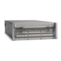
Table of Contents

Other manuals for Cisco UCS C480 M5

Questions and Answers:

Question and Answer IconNeed help?

Do you have a question about the Cisco UCS C480 M5 and is the answer not in the manual?

Cisco UCS C480 M5 Specifications

General IconGeneral
ProcessorUp to two Intel Xeon Scalable processors
ManagementCisco Integrated Management Controller (CIMC)
MemoryUp to 6 TB
Drive BaysUp to 12 x 3.5-inch or 24 x 2.5-inch
Expansion SlotsUp to 8 PCIe 3.0 slots
Power SupplyUp to four 2000W or 1600W power supplies
DIMM Slots24 DIMM slots

Related product manuals